
Precision bright light control circuit diagram

The precision bright light control circuit utilizes a Wheatstone bridge configuration to achieve stable performance under varying environmental conditions. The two-arm Wheatstone bridge, composed of resistors R1, R2, R6, and the photosensitive resistor R5, allows for precise measurement of light intensity.
In this configuration, R1 and R2 are fixed resistors, while R5, the photosensitive resistor, changes its resistance based on the ambient light level. R6 serves as a reference resistor. The balance of the bridge is affected by the resistance change of R5 as light levels fluctuate, which can be monitored through an output voltage signal.
This output can be used to control additional circuitry, such as dimming lights or activating alarms based on predefined light thresholds. The circuit's design ensures that it remains unaffected by variations in the power supply voltage, which is critical for maintaining consistent operation in different environments. Additionally, the compensation for ambient temperature changes allows for reliable performance across a range of conditions, making this circuit suitable for applications in both indoor and outdoor lighting control systems.
Overall, this precision bright light control circuit is an effective solution for applications requiring accurate light detection and control, ensuring optimal performance regardless of external factors. As shown in the circuit as a precision bright light control circuit, its work is not affected by the power supply voltage and ambient temperature. Resistors R1, R2, R6 and phot osensitive resistance R5 together constitute two-arm Wheatstone bridge.
Related Circuits
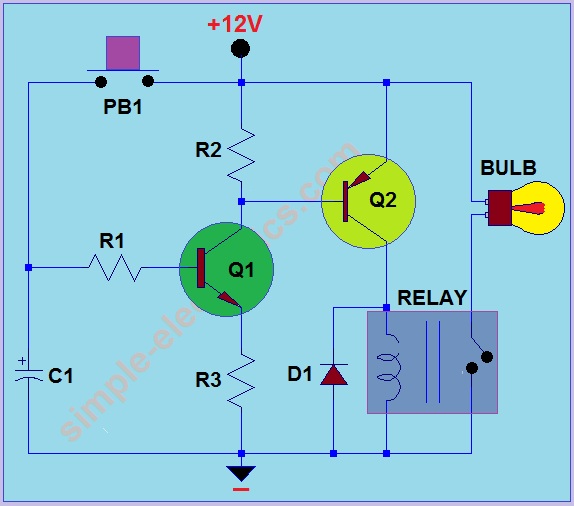
This circuit operates by activating a headlight when the push-button PB1 is pressed. The headlight remains illuminated for a predetermined duration, which can range from several seconds to minutes, before automatically turning off. When PB1 is engaged, capacitor C1...
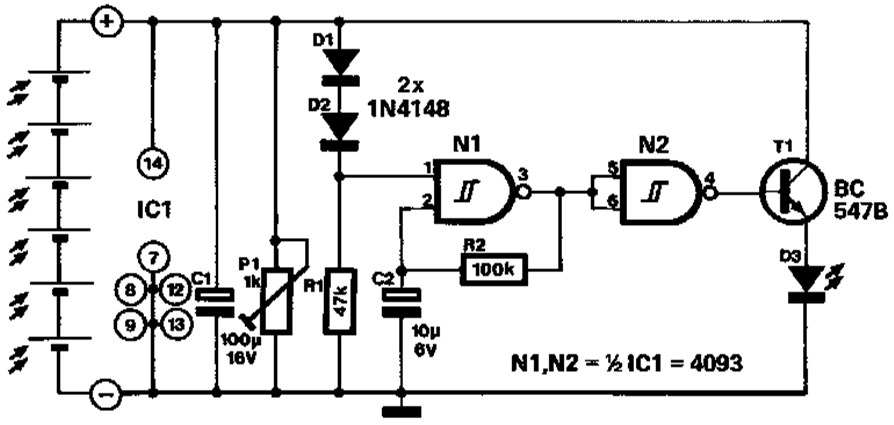
A novel application of solar cells simplifies the process of positioning a car in a garage, offering an improvement over traditional methods such as using old tires, mirrors, or chalk marks. The six solar cells depicted in Figure 1...

A DC-coupled multi-stage amplifier circuit consists of multiple stages of amplification using a DC-coupled configuration. Each stage utilizes NPN-type transistors, which are designed to maintain appropriate operating points at the base of each stage. As the signal progresses through...

This circuit utilizes a single potentiometer to control a frequency range from 300 Hz to 3000 Hz. A FET operational amplifier is employed at stages A1 and A2. The upper frequency limit is dictated by the gain-bandwidth product of...

Portable 230V lamp flasher circuit diagram. The circuit is entirely transistorized and powered by a battery. A free-running oscillator circuit is implemented using two low-power, low-noise transistors, T1 and T2. One of these transistors remains in a conducting state...

The design utilizes the LM386n-1 integrated circuit, powered by a single power supply to maintain a compact layout. There is a need to control the frequency, and the user is inquiring about which component values should be adjusted for...