
LEDs or Lamps Sequencer

This circuit implements a sequential LED or lamp illumination system, characterized by its modular design and flexibility. The basic operational principle involves a series of stages, each consisting of a small circuit dedicated to an individual LED or lamp. The sequential nature of the illumination is achieved by connecting the output of the final stage back to the input of the first stage, forming a feedback loop that allows for continuous operation.
The P1 pushbutton serves a dual purpose: it initiates the sequence upon power-on and provides a method for controlling the illumination of multiple devices simultaneously. This functionality is particularly useful in scenarios where a lengthy sequence is desired, as it allows for the selection of specific devices to remain illuminated while others are turned off. The requirement to hold P1 closed until a designated LED or lamp is illuminated ensures that the circuit is properly initialized before the sequencer begins its operation.
The design accommodates various voltage levels, with the maximum permissible input being 24V. This allows for a higher number of LEDs to be connected in series, optimizing the circuit for different applications. The use of BC337 transistors is suitable for standard current loads; however, for higher current demands exceeding 400mA, the circuit can be upgraded by substituting these transistors with more robust Darlington types, ensuring reliability and performance under increased load conditions.
This modern iteration of the circuit, leveraging advancements in semiconductor technology, offers enhanced efficiency and performance compared to earlier designs that utilized germanium transistors and low voltage lamps. The incorporation of silicon transistors and LEDs represents a significant step forward, providing a more durable and energy-efficient solution for sequential lighting applications.The purpose of this circuit was to create a ring in which LEDs or Lamps illuminate sequentially. Its main feature is a high versatility: you can build a loop containing any number of LEDs or Lamps, as each illuminating device has its own small circuit. The diagrams show three-stage circuits for simplicity: you can add an unlimited number of stages (shown in dashed boxes), provided the last stage output was returned to the first stage input, as shown. P1 pushbutton purpose is to allow a sure start of the sequence at power-on but, when a high number of stages is used, it also allows illumination of more than one LED or Lamp at a time, e.
g. one device illuminated and three out and so on. After power-on, P1 should be held closed until only the LED or Lamp related to the module to which the pushbutton is connected remains steady illuminated. When P1 is released the sequencer starts: if P1 is pushed briefly after the sequence is started, several types of sequence can be obtained, depending from the total number of stages.
* Using 24V supply (the maximum permitted voltage), about 10 LEDs wired in series can be connected to each module, about 7 at 15V and no more than 5 at 12V. * If you intend to use lamps drawing more than 400mA current, BC337 transistors should be substituted by Darlington types like BD677, BD679, BD681, 2N6037, 2N6038, 2N6039 etc.
* A similar design appeared in print about forty years ago. It used germanium transistors and low voltage lamps. I think the use of LEDs, silicon transistors, Darlington transistors and 24V supply an interesting improvement. 🔗 External reference
Related Circuits

The finish line circuit below detects the first of three cars to cross the line and illuminates a 25 watt 120 VAC lamp indicating the winning lane. Three photo transistors are used which can be embedded into the track...

The drawing below illustrates a multistage light sequencer using discrete parts and no integrated circuits. The idea is not new and I hear a similar circuit was developed about 40 years ago using germanium transistors. The idea is to...
This is a sequencer circuit. Power to the logic portion of the circuit is provided by a standard commercial "wall-wart" power adapter supplying 6 VDC. The 555 timer IC generates the pulse train that drives the chase, with timing...
This circuit operates two LED strips in pulsing mode, where one LED strip transitions from an off state to gradually lighting up, then dimming, while the other LED strip performs the opposite action. Each strip can consist of 2...
This simple and inexpensive circuit built around a popular CMOS hex inverter IC CD4069UB offers four sequential switching outputs that may be used to control 200 LEDs (50 LEDs per channel), driven directly from mains supply. Input supply of...
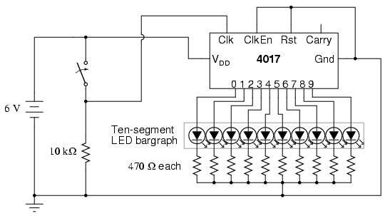
The model 4017 integrated circuit is a CMOS counter with ten output terminals. One of these ten terminals will be in a "high" state at any given time, with all others being "low," giving a "one-of-ten" output sequence. If...