
LOGIC PROBE with PULSER

The project integrates two essential tools for digital circuit diagnostics: a Logic Probe and a Logic Pulser. The Logic Probe is designed to detect the logic levels (high or low) in digital circuits, providing a visual indication through an LED or a sound signal. It can be used to troubleshoot and verify the functionality of various digital components, such as logic gates, flip-flops, and microcontrollers. The probe typically features a simple interface with a probe tip for contact with circuit nodes and a ground connection.
The Logic Pulser, on the other hand, is used to generate test signals, allowing the user to inject known logic levels into a circuit. This tool is particularly useful for testing the response of digital components to specific inputs, enabling designers to observe how circuits behave under different conditions. The pulser can be configured to produce square waves or single pulses, which can be adjusted for frequency and duration, depending on the testing requirements.
The combination of these two tools in a single device enhances the efficiency of the design and debugging process. The schematic for this project would typically include a microcontroller to manage the logic levels and signal generation, along with a series of resistors, capacitors, and transistors to form the necessary circuits for both the Logic Probe and Logic Pulser functionalities. Power supply considerations are also crucial, ensuring that the device operates within the specified voltage range for safe testing of various components.
In summary, this project serves as a versatile tool for engineers and hobbyists alike, facilitating the testing and verification of digital circuits by combining the functionalities of a Logic Probe and a Logic Pulser into one compact device.This project is a combination Logic Probe and Logic Pulser. It is capable of testing all sorts of digital and microcomputer projects. You will find it extremely handy when designing a project as the golden rule is to test everything in steps and stages during the design-and-construction process. If you are not sure how a Logic Probe or Pulser works, let me explain. 🔗 External reference
Related Circuits
An RF probe is a circuit designed for testing equipment that converts high-frequency signals into DC voltage. This conversion facilitates the measurement of RF voltages for testing or adjusting transmitters, receivers, and modulators. The RF probe circuit outlined here...
An RF probe is used to directly measure the level of RF voltage present at a particular point and is one of the most useful test instruments in the hands of the home brewer. It is normally used with...
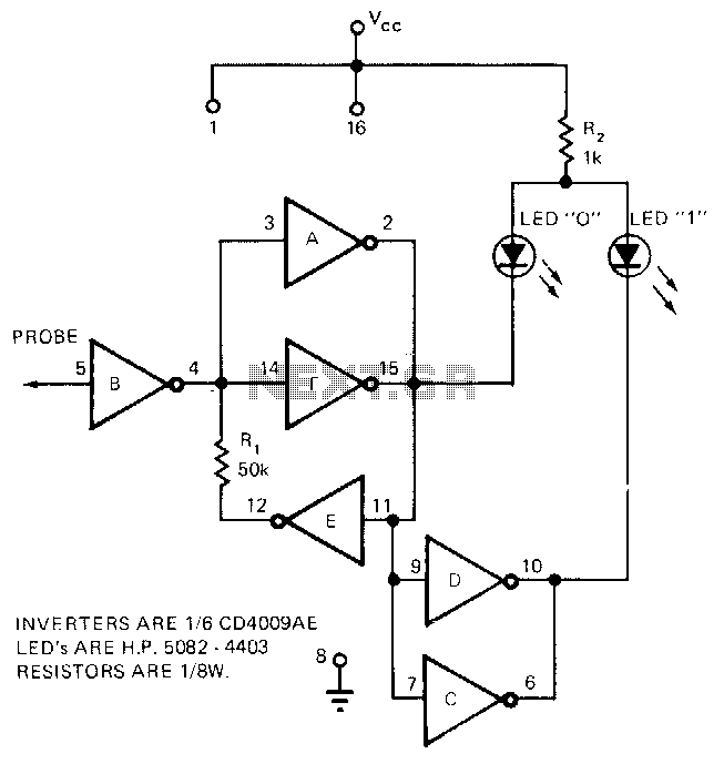
The circuit requires only the CD4009AE hex buffer, two resistors, and two LEDs to create a logic probe. This CMOS logic probe has an input impedance of 10^12 ohms and operates within a voltage range of 3 to 15...
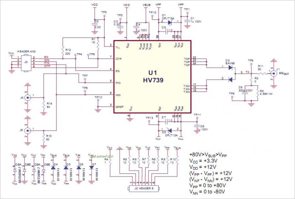
This demo board data sheet explains how to utilize the HV758DB1 to produce a fundamental high voltage pulse waveform for use as an ultrasound transmitting pulser. The HV758 circuit employs a DC coupling method in all level translators, eliminating...
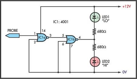
This simple logic probe has both LEDs illuminated with no signal at the input. However, due to the NOR gates connected to the probe, it indicates correctly when a high or low signal is present. It also functions correctly...
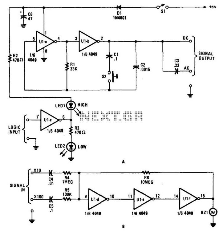
This circuit for a test set contains a signal injector (U1A/U1B) and associated components, a logic probe (U1C), and an audio amplifier. SI selects either 10-kHz or 100-Hz output. U1D, U1E, and U1F form an audio amplifier that drives...