
Make your own Boston Bomb

The described circuit involves a DC-DC converter, which is a type of power supply circuit that converts a source of direct current (DC) from one voltage level to another. This converter can either step up (boost) or step down (buck) the input voltage, depending on the design requirements. The use of a PIC 16F84 or PIC 16F88 microcontroller indicates that the circuit may include programmable features, allowing for greater control and flexibility in operation.
The PIC microcontroller serves as the control unit for the DC-DC converter. It is responsible for managing the switching elements within the converter, regulating output voltage, and ensuring efficient operation through pulse-width modulation (PWM) techniques. The choice between the PIC 16F84 and PIC 16F88 may depend on the specific application requirements, such as the need for additional I/O pins or memory capacity.
SW1, the test switch, is integrated into the circuit to facilitate testing and debugging. When pressed, it may initiate a specific function within the circuit, such as enabling the converter, resetting the microcontroller, or triggering a diagnostic routine. This feature is essential during the development phase to ensure that the circuit operates as intended and to troubleshoot any potential issues.
In summary, the circuit diagram represents a versatile DC-DC converter controlled by a microcontroller, with a test switch included for operational verification. The design is suitable for applications requiring efficient power conversion and programmable control, making it a valuable component in various electronic systems.This is the circuit diagram. It is essentially a DC-DC converter, and a PIC 16F84 (or PIC 16F88) to drive it. Sw1 is a test switch - push it to caus.. 🔗 External reference
Related Circuits
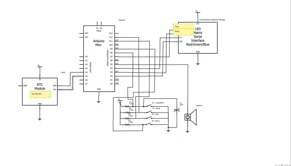
The device is designed to promote respectful time management during meetings, particularly useful in ship-room or SCRUM meetings. The following is a list of components required, including links for purchasing specific parts. It is advisable to check eBay or...
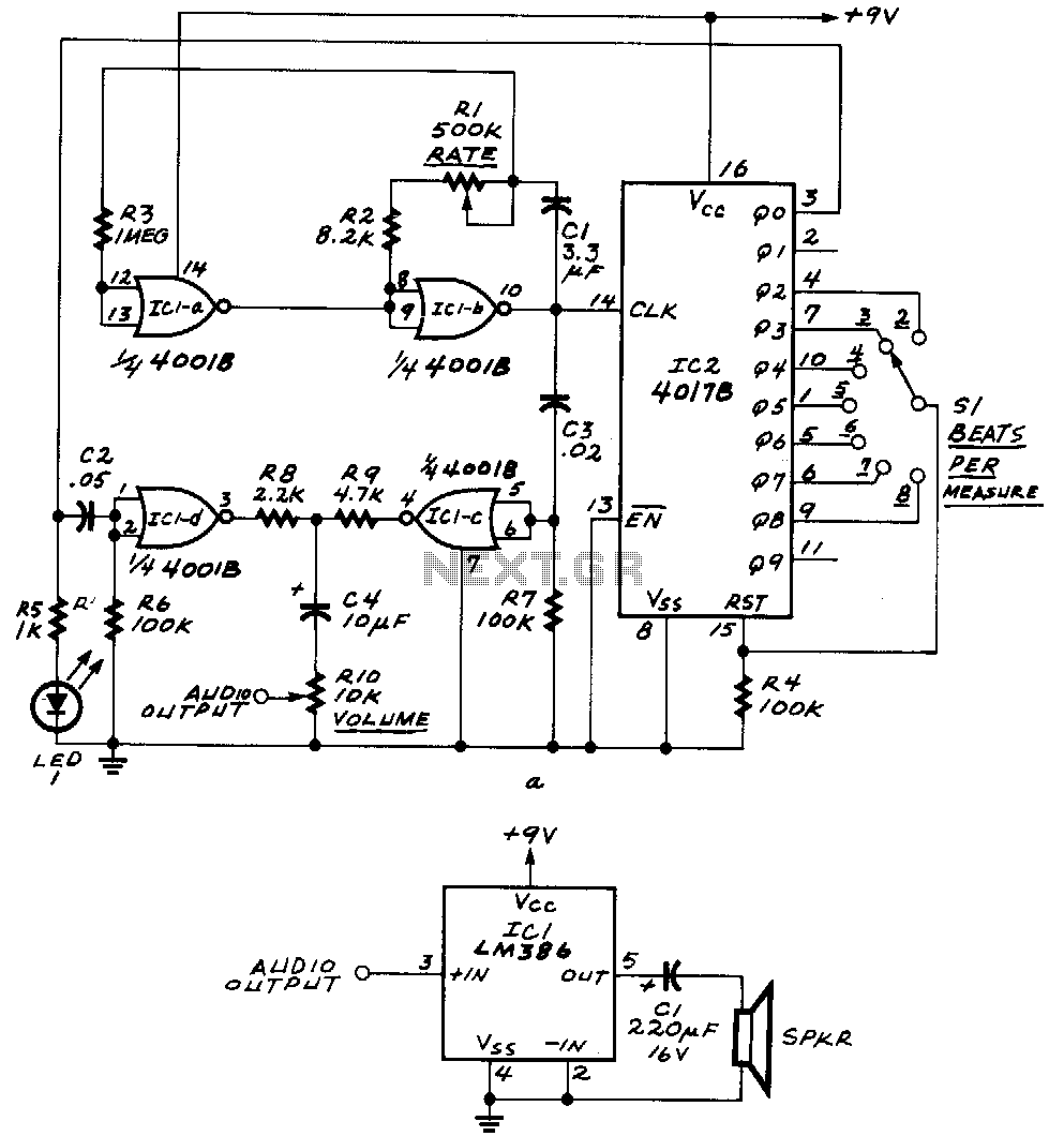
ICla and IClb form an astable multivibrator. The astable's signal is fed to IC1c, as well as to the clock input of IC2, a 4017B decade counter. The outputs Q0 through Q9 of that IC become high one at...
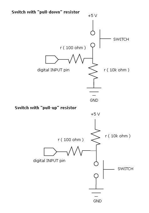
Most beginners in digital electronics assume that a floating input represents a logic 0, which is a misconception. Floating inputs are in a neutral state and can represent either a logic 0 or a logic 1. This misunderstanding can...

Consider a capacitor with capacitance C that charges to a voltage V and discharges to 0V at a frequency of 5 times per second. To estimate the average current, also referred to as the RMS current, a rough approximation...
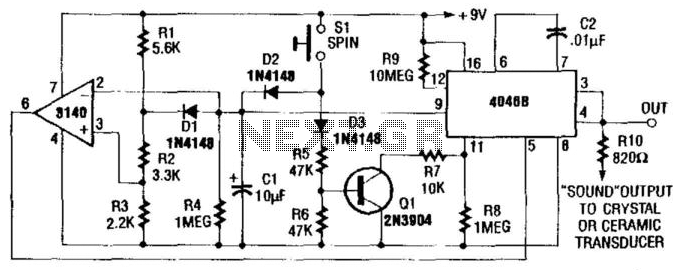
Used in electronic roulette or dice games, this circuit produces a clock signal that initially is several tens of kHz (depending on C2) and gradually decreases to zero in about 15 seconds, as C1 discharges through R4. The described circuit...
Switch-mode power supplies are utilized in electronic circuits to efficiently increase (step up) or decrease (step down) voltage levels. In comparison to linear voltage regulators, switch-mode supplies convert minimal energy into heat, resulting in high efficiency. This characteristic is...