
Metronome with CA741

This circuit utilizes two CA741 operational amplifiers to generate a distinctive sound effect characterized by a "tick" sound. The first op-amp is configured in an astable multivibrator configuration, producing continuous timing pulses. The frequency of these pulses is determined by the timing components, which include capacitor C1, resistor R2, and variable resistor VR1. The astable configuration allows for the generation of square wave signals, where the duty cycle can be adjusted using VR1.
The output from the first op-amp is coupled to the second op-amp through capacitor C2. This coupling allows for AC signal transmission while blocking any DC components. Additionally, the output is directly coupled to transistor Q1 via the zener diode ZD1. The role of the zener diode is to provide a reference voltage, ensuring that Q1 operates correctly in response to the output pulses from the first op-amp.
The second op-amp is configured as an integrator, which processes the square wave output from the first op-amp. This configuration effectively distorts the square wave into a triangular waveform, contributing to the overall sound effect. The integration process introduces a ringing effect, which enhances the characteristic "tick" sound produced by the circuit.
The output pulse generated by the first op-amp triggers the conduction of the zener diode and transistor Q1 upon each positive transition. The resistor R8, valued at 1k ohms, serves to limit the current flowing through Q1, ensuring safe operation and preventing potential damage to the transistor. This current limiting is crucial for maintaining the integrity of the circuit while achieving the desired sound effect.
Overall, this circuit design is a creative application of operational amplifiers and passive components to produce a unique auditory effect, suitable for various electronic sound applications.This circuit uses a couple of Op-amps to produce an interesting sound effect. The left hand CA741 is wired as a standard astable and produces the timing pulses, controlled by C1, R2 and VR1. The output is fed via C2 to the second op-amp and is also direct coupled via the zener ZD1 to Q1. The right hand CA741 is configured as an integrator, its purpose being to distort the output pulse from the first op-amp.
This produces a ringing effect on the output pulse and gives the circuit a characteristic "tick" sound. The output pulse at the first op-amp will cause the zener and Q1 to conduct on every positive transition.
The 1k resistor R8 then acts as a 🔗 External reference
Related Circuits
An external piezoelectric element has been added for placement on a bench top, making it more accessible for children. This external piezo element was soldered to the same pads as the built-in piezo element of the Tap-Tempo Metronome. A...
This circuit utilizes two operational amplifiers (op-amps) to create a unique sound effect. The first op-amp, CA741, is configured as a standard astable multivibrator, generating timing pulses controlled by components C1, R2, and variable resistor VR1. The output from...
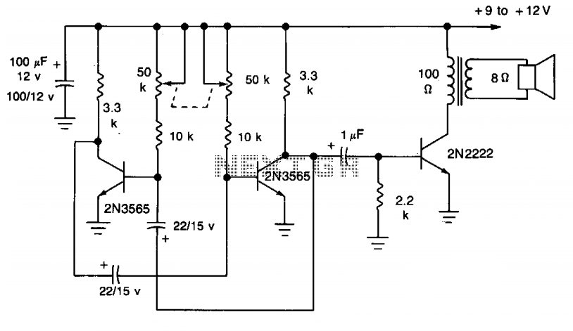
This simple circuit utilizes a multivibrator to generate beats, followed by an audio amplifier stage to enhance the output level. The range of adjustment is approximately from 40 to 200 beats per minute, controlled by a gauged potentiometer. The described...

Q1 & Q2 provide linear frequency operation of IC1 following P1 resistance variation. Q3 was added in order to obtain a louder click, similar to clockwork metronomes. A 12V micro battery was used to obtain a higher output power...
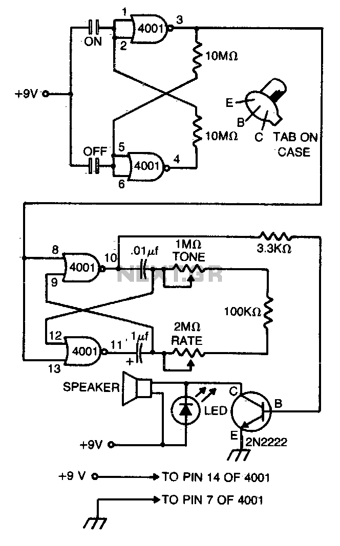
This compact metronome operates for years on a single nine-volt transistor battery. It features both tone and pulse rate controls and utilizes touch plates for starting and stopping. The device can be housed in a case no larger than...
The typical BPM range for music is between 40 and 240 BPM, corresponding to periods of 1500 ms and 200 ms, respectively. A BPM of 120 equates to a period of 500 ms. The circuit requires a resistor R4...