
Night Light Saver
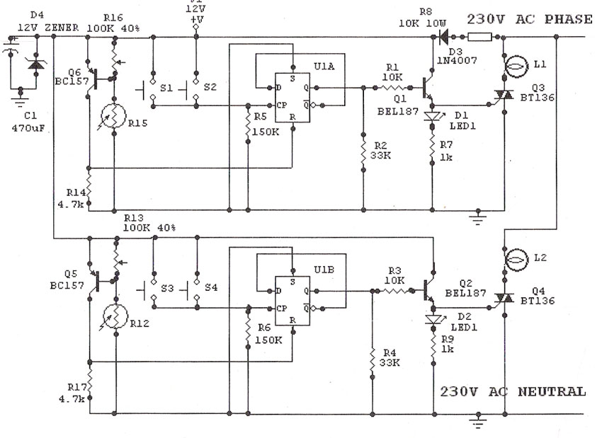
The Saver V5.0 is a microcontroller-based circuit designed to emulate a clock function for controlling a night light. The primary component of the circuit is the AT89C2051 microcontroller, which is responsible for executing the clock emulation program and managing the on/off operation of the night light based on pre-defined time settings. The microcontroller operates with an external oscillator, which is generated using a Schmitt trigger gate (CD4093). This configuration produces a stable clock signal at approximately 680 kHz, which is essential for accurate timing operations.
The circuit is designed to switch the night light on at 19:00 and off at 22:00 daily, providing a simple solution for automated lighting control. The time setting can only be adjusted at 18:00 by pressing a designated time set button. This limitation ensures that the user does not inadvertently change the schedule at other times of the day. In the event of a power failure, the circuit is designed to indicate this condition through a high-rate blinking LED. This feature alerts the user to the need for manual intervention, as the system does not include a battery backup to retain settings during power outages.
The output stage of the circuit is capable of driving a load of up to 25 watts, making it suitable for controlling standard night lights or similar devices. The design emphasizes low cost and ease of installation, making it accessible for various applications. Additionally, the circuit is engineered to minimize electromagnetic interference (EMI), ensuring that it operates quietly without affecting nearby electronic devices. Overall, the Saver V5.0 presents a straightforward and efficient solution for automated lighting control with minimal complexity and cost.The Saver V5.0 runs simple clock emulation program, turns a night light on and off with preset time, say 19:00 to 22:00 everyday. The design features low cost, easy installation, no battery backup and no EMI. The AT89C2051 uses external oscillator generated by schmitt trigger gate CD4093, ~680kHz. Reference frequency was derived from 50Hz main line. Time setting only allows at 18:00 by pressing time set button once. If main line has failed, functioning LED will blink at high rate . Since there is no battery backup, thus repressing the button is then needed. The output is capable of driving say, a 25W 🔗 External reference
Related Circuits
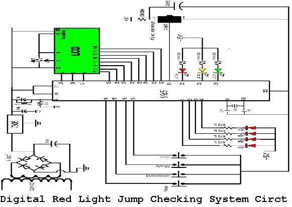
A digital red light jump checking system with an RF transmitter. This project allows for the tracking of vehicles that run red lights by capturing their license plate numbers and the time of the violation. The digital red light jump...
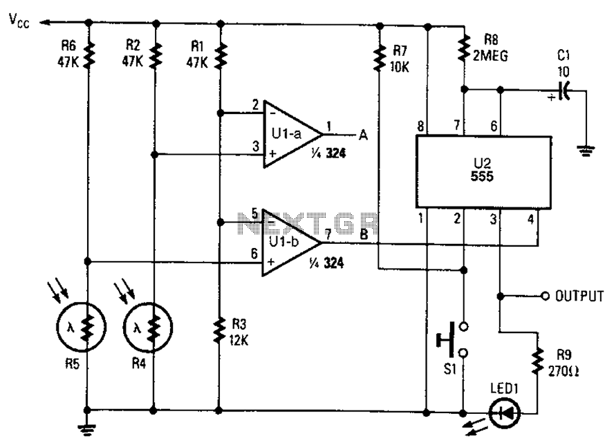
A combined monostable multivibrator using the 555 timer integrated circuit, along with a pair of light control comparators. This circuit can be utilized to control a load based on the timing parameters set within the circuit. The circuit comprises a...
The automobile interior lights fader circuit diagram is designed to gradually brighten and dim the interior lights of older vehicles. This circuit utilizes the LM324 low-power operational amplifier as its core component. The automobile interior lights fader circuit is an...
Light Sensitive Staircase Switch with Triac. The operation of the third circuit is similar, except that it incorporates photo sensitivity. The circuit is illustrated in the schematic. When there is insufficient light... A light-sensitive staircase switch utilizing a TRIAC is...
The LED traffic Light circuit controls 6 LEDs (red, yellow and green) for both north/south directions and east/west directions. The timing sequence is generated using a CMOS 4017 decade counter and a 555 timer. Counter outputs 1 through 4...
This simple and inexpensive circuit is not limited to Christmas use. It consists of two resistors, a small-signal transistor such as a BC547, and a flashing LED. The circuit operates by utilizing a small-signal transistor, which acts as a switch...