
On Indicator

The circuit design centers around three primary components: the square wave generators and the inverter. The first generator (N1) is configured as a timer that produces a low-frequency square wave with a period of roughly two minutes. This pulse serves as the timing reference for the entire circuit. The pulse duration is set to approximately 10 seconds, during which the second generator (N2) becomes active.
N2 is designed to output a series of pulses at a frequency of one pulse per second. Over the course of the 10 seconds activated by N1, N2 generates a total of 10 pulses. These pulses are then fed into an inverter (N4), which is configured to only respond during the active period of N1. The inverter's function is to convert the incoming pulses from N2 into a form that can drive an audible output, specifically a buzzer.
The buzzer, typically a ToKOhm type or similar, is connected to the output of N4. As N4 toggles its state in response to the pulses from N2, it activates the buzzer to produce a series of beeps. This auditory feedback serves as a reminder that the device is still powered on, helping to prevent unintentional battery drain.
Component selection is flexible, as the circuit is tolerant to variations in component values. This allows for customization based on the user’s preferences or specific application requirements. The circuit is designed to draw minimal current, ensuring that it does not significantly impact the overall battery life of the device. This design approach provides an efficient and effective solution for battery-operated devices, minimizing the risk of dead batteries due to forgetfulness. Battery-operated equipment can work on one set of batteries for a long time nowadays. However, if it is left on inadvertently, that "long time" is over very quickly. Moreover, flat (dead) batteries are always found at the wrong moment. The circuit proposed here is a sort of aide-memoire. Every two minutes, it emits 5 to 10 pips to indicate that the equipment is still switched on. Basically, the circuit consists of three rectangle-wave generators and an inverter. The first of the generators is formed by N1 and provides a signal with a period of about two minutes and a pulse duration of around 10 seconds. During those 10 seconds, the second generator starts operating in a one-second rhythm. Thus, N2 outputs 10 pulses every 2 minutes. That output is inverted so that N4, like N2, can only be enabled during the 10-second pulse train from Nl.
The difference is that during those 10 seconds, N4 is enabled and inhibited 10 times; this is what causes the pips. Do not take the times and number of pulses too literally, because wide variances are between ICs from different manufacturers.
On the other hand, component values are not critical, so it is fairly easy to adapt the circuit to personal taste or requirements. The buzzer can be a standard ToKOhm type or equivalent. The current drawn by the circuit is negligible.
Related Circuits
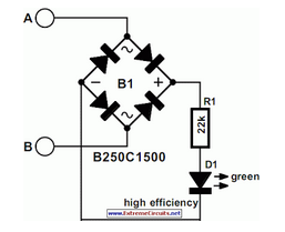
The operating principle of the circuit is very simple. The first LED D1 is placed in series with the resistor R2 and diode D4. An only be lit this LED indicates that the battery is ypofortismeni. For this reason,...
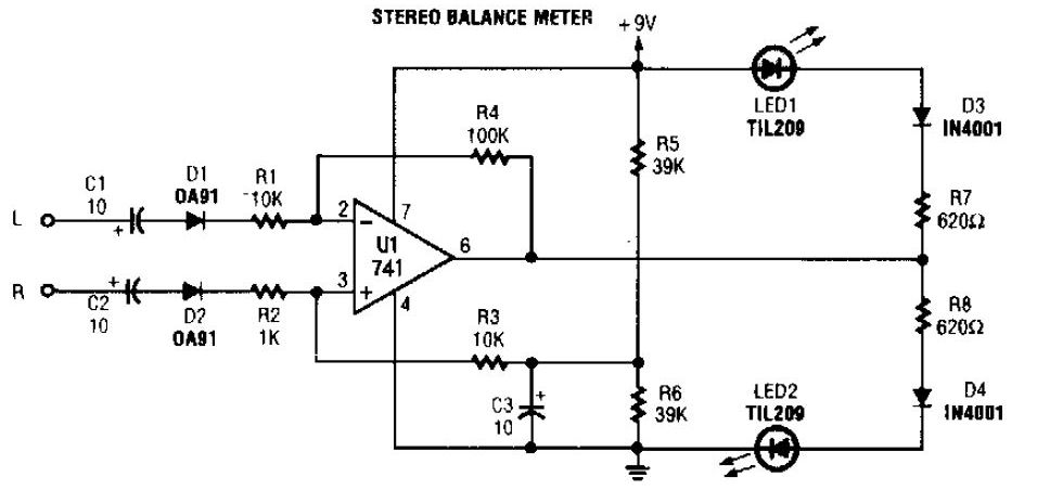
The simplest stereo balance meter circuit schematic available on the internet. When the left and right signals are equal, no output is present from U1 and pin. This stereo balance meter circuit is designed to visually indicate the balance between...
Today, nearly all computers are equipped with logic blocks designed to implement a USB port. In practice, a USB port can deliver over 100 mA of continuous current at 5V to the peripherals connected to the bus. This capability...
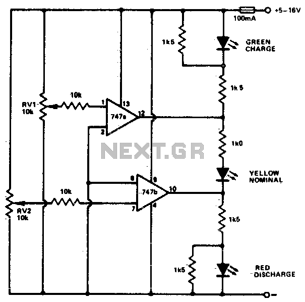
This circuit monitors car battery voltage and indicates nominal supply voltage, as well as low or high voltage conditions. RV1 and RV2 are used to adjust the thresholds at which the red/yellow and yellow/green LEDs activate or deactivate. For...
While owning a modern NiCd battery charger, there may still be instances where an incompatible battery is encountered, such as one with a unique voltage requirement or one that necessitates a higher charging current than what a standard charger...
The modem off indicator is designed specifically for avid Internet users. It is evident that the circuit for this indicator is quite simple. The modem off indicator serves a crucial function for users who rely heavily on internet connectivity. This...