
One transistor audio mixer

The circuit design involves a transistor amplifier configuration where three or more input signals are managed through individual level control mechanisms before being directed to the base of the transistor Q1. This arrangement allows for the adjustment of the signal levels to optimize the overall performance of the amplifier. The transistor Q1 functions as a voltage amplifier, providing a significant voltage gain of 20, which indicates that the output voltage will be 20 times greater than the input voltage, assuming ideal conditions.
In this configuration, the individual level controls can be implemented using potentiometers or variable resistors, allowing the user to fine-tune each input signal's amplitude before amplification. The base of Q1 is connected to a resistor network that helps set the biasing conditions of the transistor, ensuring it operates in the active region for linear amplification.
Additionally, proper coupling capacitors may be employed at the input stage to block any DC offset from the input signals while allowing the AC components to pass through. This will help maintain the integrity of the input signals during amplification. The collector of Q1 will be connected to a load resistor, which, in conjunction with the transistor’s characteristics, determines the output voltage swing.
The output can be further processed or sent to subsequent stages of amplification or signal processing, depending on the application requirements. Careful consideration must be given to the power supply voltage and current ratings to ensure reliable operation of Q1 and to prevent distortion or clipping of the amplified signal.Three or more inputs with individual level controls feed into the base of Q1 that provides a voltage gain of 20.
Related Circuits
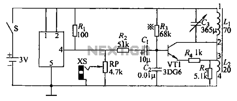
An audio frequency signal generator can output audio signals, 465 kHz spectral amplitude signals, and 52.5 Hz to 16 kHz high-frequency amplitude-modulated signals. The high-frequency oscillator's vibration frequency is determined by the components G and L. A variety of...
This unit is an upgrade of the previous phone call interceptor. Instead of using an answering machine to provide the outgoing message and recording functions, it uses the ISD4004 (from Windbond Electronics). The ISD4004 records up to 8 minutes...
The LED flasher circuit operates by flashing an LED using only a 1.5-volt power supply. Typically, a power supply of more than 2 volts is required for an LED to function. The LED flasher circuit designed for operation at 1.5...
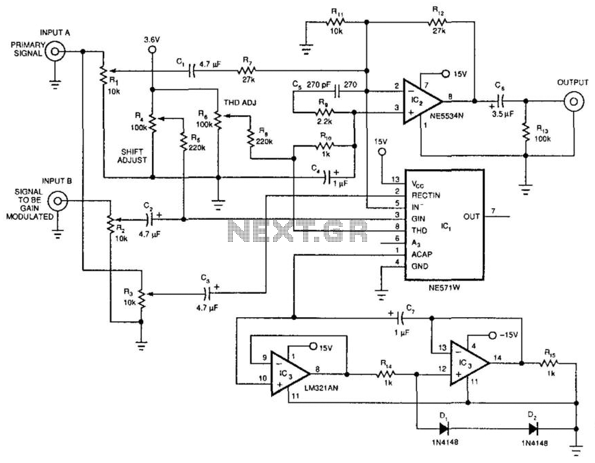
The dynamic mixer combines two audio inputs by adding the primary signal, Input A, to a gain-controlled signal, Input B. The unique feature of this circuit is that the average voltage level of Input A controls the gain of...
A lot of friends asked me to draw a more shrunk circuit 2-ch mixer, which will contain also, operation CROSSFADER. The circuits can be modified and added also other channels, repeating basic that I give. It can be added...
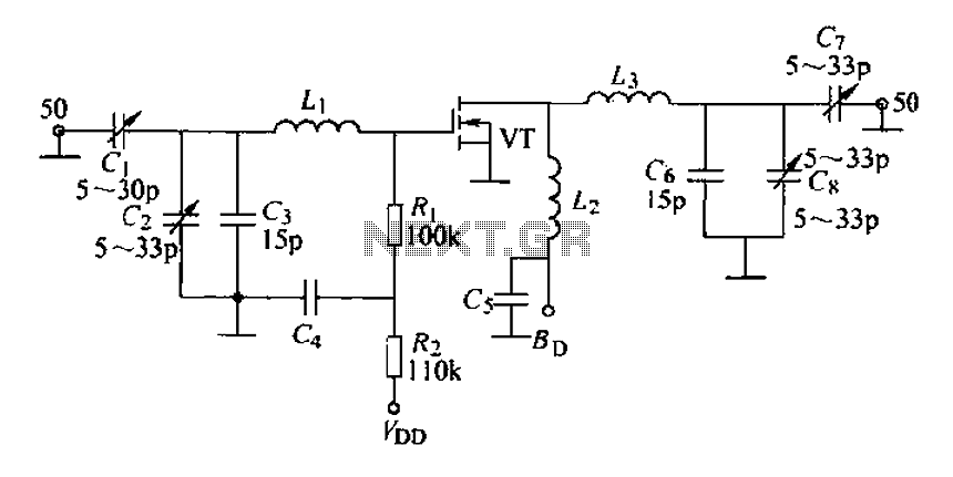
A 175 MHz high-frequency amplifier circuit utilizing a field-effect transistor (FET) is presented. The field-effect transistor used is the 3D04H, along with its associated components and parameters. The 175 MHz high-frequency amplifier circuit is designed to amplify signals in the...