
Ratio discriminator circuit

The common phase frequency detector serves as a critical component in various communication systems, enabling the extraction of frequency information from modulated signals. The mutual coupling and capacitive coupling methods allow for flexibility in design based on the specific requirements of the application. The improved mutual coupling ratio discriminator circuit, incorporating the 2AP9 diode, enhances performance by providing better sensitivity and stability.
The use of capacitors C3 and C4 in the detection process allows for effective filtering of the signal, ensuring that only relevant frequency components are processed. The strategic placement of resistors at point D facilitates the separation of output voltages, minimizing interference and ensuring clear signal representation. The connection of a large capacitor G at outputs A and B plays a pivotal role in stabilizing the output voltage during rapid amplitude changes, which is crucial in maintaining signal integrity in dynamic environments.
The inclusion of diodes in the circuit design is essential for ensuring that the output voltages from the two detectors remain in phase, allowing for coherent summation. This design choice enhances the overall reliability of the frequency detection process, making it suitable for applications requiring precise frequency tracking and phase comparison. The comprehensive design considerations taken in this circuit make it a robust solution for phase frequency detection in modern electronic systems. Common phase frequency detector can be divided into mutual coupling and capacitive coupling frequency discriminator frequency discriminator according to their coupling. Its imp roved mutual coupling ratio discriminator circuit is shown in the figure, the diode is 2AP9 2. z- phase discriminator in an AM-FM FM wavelet transform parts of the same, but there are significant changes in the detector section. To type differences are: 1) the detection of two capacitors C3 and the connection point O C4 and two resistors connected point D separate frequency discriminator output voltage two from D, E remove points.
2) at the output A, B and connected at both ends of a large capacitance G, the electrical capacity of about lOyF, because of the time (R. + R2) C circuit constant number of large, about (o.1 ~ o .2) s, so that the detection process, for more than 15Hz amplitude changes, Udc on the capacitor G remained unchanged.
3) two diodes, one diode and phase frequency discriminator in the connection in the opposite direction. So in addition to ensure that the two diodes DC path, but also makes the two detector output voltage polarity become identical.
Thus, a two detectors at both ends of the output voltage is the sum.
Related Circuits
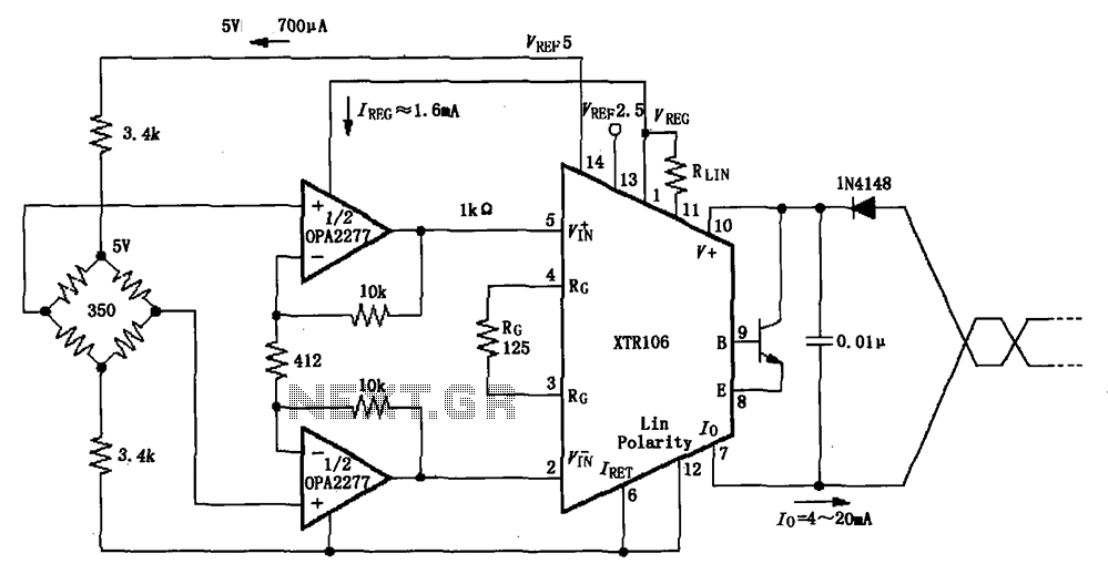
The XTR106, as illustrated in the figure, features two internal source voltages of 2.5V and 5V, enabling it to accommodate a wide range of bridge values without the need for additional circuitry. It can operate with bridge resistances lower...
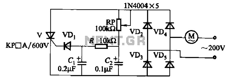
The circuit illustrated in Figure 3-11 employs a unidirectional thyristor control mechanism. An adjustable potentiometer, designated as RP, is utilized to continuously modify the motor speed. The circuit utilizes a unidirectional thyristor, also known as a silicon-controlled rectifier (SCR), which...
The inquiry pertains to identifying the component within the circuit that regulates the minimum RPM achievable. The current operational range of the motor is between 1400 and 3700 RPM, and there is an interest in modifying the circuit to...

Many brands in Asia utilize ultrasonic remote control switch circuits, with some employing relays and others utilizing thyristors. The remote control transmitter is of a puffer type, featuring an ultrasound flute with both olive and flat circular shapes. This...
This is a solar tracking circuit designed to harness power from sunlight. The circuit operates optimally by maximizing sunlight exposure to generate electricity. The solar tracking circuit utilizes a combination of photovoltaic (PV) cells, sensors, and a microcontroller to adjust...
The circuit presented is designed to prevent burning one's tongue by monitoring the temperature of coffee. It consists of a voltage regulator, a temperature-to-voltage converter, a comparator, and two LEDs. In general, the circuit operates as follows: if the...