
Keypad Combination Lock circuit
C1 1 1uF 25V Electrolytic Capacitor
C2 1 220uF 25V Electrolytic Capacitor
R1 1 2.2K 1/4W Resistor
Q1 1 2N3904 NPN Transistor 2N2222
D1 1 1N4148 Rectifier Diode 1N4001-1N4007
K1 1 12V SPDT Relay Any appropriate relay with 12V coil
U1 1 LS7220 Digital Lock IC
S1-S12 12 SPST Momentary Pushbutton Keypad (see notes)
HD1 1 12 Position Header
Notes
To set the combination, wire the appropriate switches to U1 pins 3, 4, 5 and 6 using the header. For example if S1 was connected to pin 3, S2 to pin 4, S3 to pin 5 and S4 to pin 6, the combination would be 1,2,3,4. Now wire all other unused switches across the header to pin 2 of U1. In this way you can create any 4 digit combination you want. Pin 2 is the reset pin, so connecting all unused keys to it assures that the entire combination must be reentered if an incorrect key is pressed. When the appropriate combination is entered, the relay is activated for a period of time determined by C1. The 1uF capacitor specified in the parts list will result in an on-time of roughly 5 seconds. Increase the value of C1 to increase this time. An easy way to make a keypad is to buy 12 PC board mount pushbuttons and then etch a PC board so that the buttons are in 4 rows of 3, similar to a telephone keypad. Place this in a case and then use a label maker or transfer letters to add your numbers to the tops of the pushbuttons. You can also use a pre made keypad but keep in mind that you need a pad which provides an output for each key. Most pads available have the keys connected to provide a row and column signal when they are pressed.
The circuit operates as follows: Upon powering the circuit, the LS7220 Digital Lock IC (U1) awaits input from the keypad composed of 12 momentary pushbuttons (S1-S12). Each pushbutton corresponds to a digit in the combination. The configuration of the pushbuttons is crucial, as it determines the specific combination that will activate the relay (K1). The wiring of the pushbuttons to pins 3, 4, 5, and 6 of U1 allows for a flexible combination setup, while pin 2 serves as a reset point to ensure security; if any incorrect button is pressed, the user must start over.
When the correct sequence is entered, U1 activates the transistor (Q1), which in turn energizes the relay (K1) for a duration dictated by the timing capacitor (C1). The choice of a 1uF capacitor provides an approximate activation time of 5 seconds, which can be modified by using a larger capacitance to extend the relay's on-time. The relay can then control various devices, such as solenoids or motors, allowing for a wide range of applications from locking mechanisms to automated doors.
The additional capacitor (C2) may be used for stabilizing voltage levels in the circuit, ensuring reliable operation of the LS7220 and other components. The rectifier diode (D1) protects the circuit from potential back EMF generated by the relay coil, safeguarding the digital lock IC and other sensitive components. The inclusion of a header (HD1) facilitates easy connections for the keypad and additional components, streamlining the assembly process. Careful attention to the layout and connections will enhance the reliability and functionality of this combination lock circuit.This simple circuit is the electronic version of the combination lock. Using the special purpose LS7220 digital lock IC, the circuit allows a 4 digit combination of your choice to activate a relay for a set period of time. This relay can then be used to trigger a lock solenoid, enable a starter button, open a motorized door, or many other tasks that require a momentary signal.
C1 1 1uF 25V Electrolytic Capacitor C2 1 220uF 25V Electrolytic Capacitor R1 1 2.2K 1/4W Resistor Q1 1 2N3904 NPN Transistor 2N2222 D1 1 1N4148 Rectifier Diode 1N4001-1N4007 K1 1 12V SPDT Relay Any appropriate relay with 12V coil U1 1 LS7220 Digital Lock IC S1-S12 12 SPST Momentary Pushbutton Keypad (see notes) HD1 1 12 Position Header Notes To set the combination, wire the appropriate switches to U1 pins 3, 4, 5 and 6 using the header. For example if S1 was connected to pin 3, S2 to pin 4, S3 to pin 5 and S4 to pin 6, the combination would be 1,2,3,4.
Now wire all other unused switches across the header to pin 2 of U1. In this way you can create any 4 digit combination you want. Pin 2 is the reset pin, so connecting all unused keys to it assures that the entire combination must be reentered if an incorrect key is pressed. When the appropriate combination is entered, the relay is activated for a period of time determined by C1.
The 1uF capacitor specified in the parts list will result in an on-time of roughly 5 seconds. Increase the value of C1 to increase this time. An easy way to make a keypad is to buy 12 PC board mount pushbuttons and then etch a PC board so that the buttons are in 4 rows of 3, similar to a telephone keypad. Place this in a case and then use a label maker or transfer letters to add your numbers to the tops of the pushbuttons.
You can also use a pre made keypad but keep in mind that you need a pad which provides an output for each key. Most pads available have the keys connected to provide a row and column signal when they are pressed.
🔗 External reference
Related Circuits
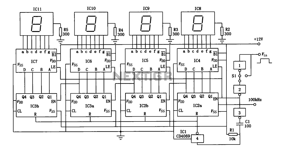
A digital pulse width measurement circuit is presented. It operates with a 100 kHz reference frequency to count the pulse width of the input signal. The count value represents the measured pulse width displayed on four seven-segment LED displays....
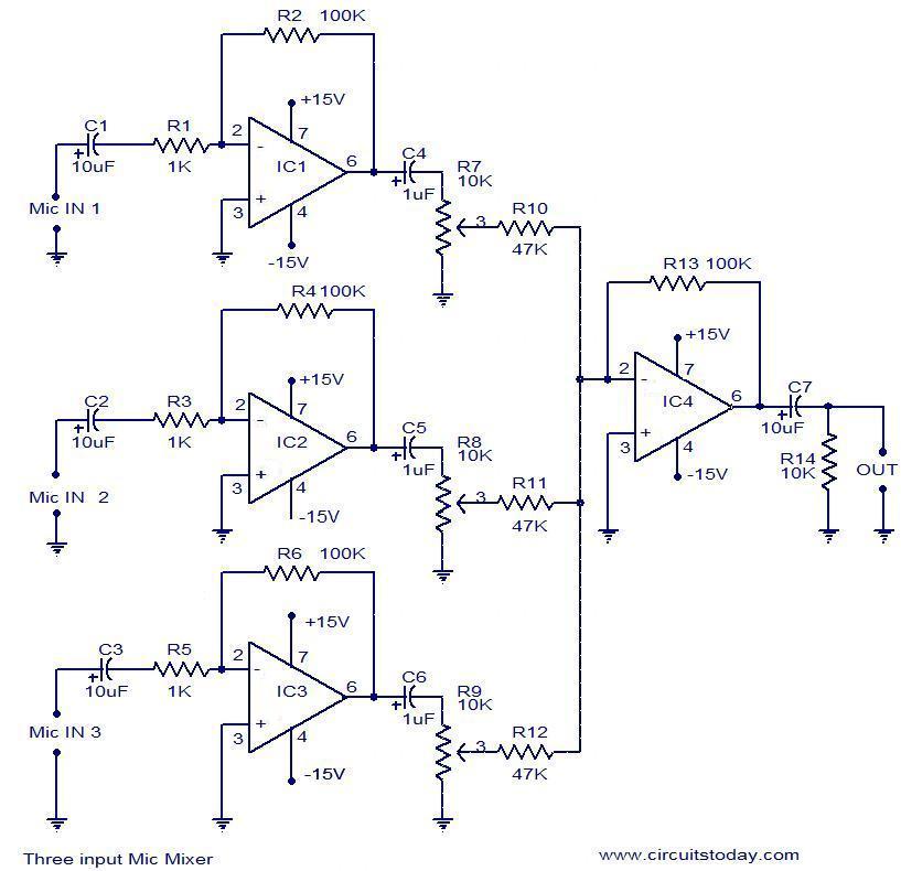
This document outlines a simple three-input microphone mixer circuit utilizing the widely used uA741 integrated circuits (ICs). Four uA741 ICs are employed in this design. IC1, IC2, and IC3 function as preamplifiers, each providing a gain of approximately 40...
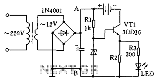
A practical single-tube constant current charger is illustrated, utilizing a transistor (VT1) that plays a crucial role in maintaining a constant current. The current value is determined by the voltage regulator and resistor R2. The general output voltage is...
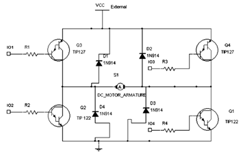
The diagram below illustrates an H-Bridge circuit featuring four inputs and an external power supply. The control application must enable the motor to operate in both forward and reverse directions. The H-Bridge is a crucial component in motor control applications,...
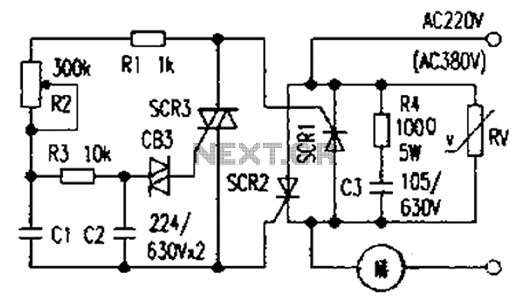
The presentation of a general power thyristor trigger circuit is more complex, and some components are difficult to procure. A successful trigger circuit has been constructed for only a few dollars. This circuit is designed to trigger a thyristor...

This is a design of the circuit diagram for an RS422 interface. Connector K1 is connected to the serial port of the PC, and power for the PC side of the circuit is obtained from the signal lines DTR...