
Electronic CD4017 CD4066 the switch circuit diagram

The CD4017 is a decade counter integrated circuit (IC) that can drive up to ten outputs, sequentially activating them based on clock pulses. It is commonly used in applications requiring counting and sequencing. Each output pin (Q0 to Q9) goes high in response to a clock signal, allowing for the control of various devices or circuits.
The CD4066 is a quad bilateral switch IC that can control analog or digital signals. It contains four independent switches that can be used to connect or disconnect signals from a circuit. The switches are controlled by digital signals, allowing for versatile applications in signal routing and manipulation.
In the switch circuit diagram utilizing both the CD4017 and CD4066, the output pins of the CD4017 can be connected to the control inputs of the CD4066 switches. This configuration allows the activation of specific switches based on the counting sequence of the CD4017. For instance, as the CD4017 counts from 0 to 9, it can enable different paths in the circuit, effectively routing signals through the CD4066 switches.
To implement this circuit, the CD4017 would be connected to a clock source, which could be a simple oscillator circuit generating pulses. The outputs of the CD4017 would then connect to the control pins of the CD4066. The input signals to the CD4066 would be routed from the source, and the outputs could lead to various destinations, such as LEDs, motors, or other electronic components.
This configuration allows for dynamic control of multiple outputs using a single clock signal, making it ideal for applications in timing, sequencing, or automated control systems. The combination of the CD4017 and CD4066 provides a flexible and efficient means of managing multiple signal paths in electronic designs.Electronic CD4017, CD4066 constitute the switch circuit diagram:
Related Circuits
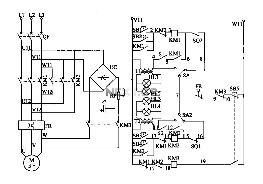
The electric valve control circuit consists of three main parts: the main lines, control lines, and power consumption brake line. The main circuit includes a power switch (QF), three-phase AC contactors (KM1, KM2), a thermal relay (FR), and a...
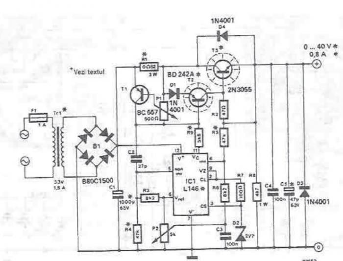
An adjustable laboratory power supply capable of providing an output voltage range from 0 to 60 volts can be constructed using the provided circuit diagram. This power supply can utilize the LM723 chip for lower voltage applications or, for...
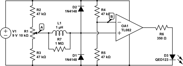
The circuit above is a canonical AC coupled common emitter amplifier, which is typically used as a linear amplifier rather than a switch that activates when the input exceeds a certain level. The AC coupled common emitter amplifier is...
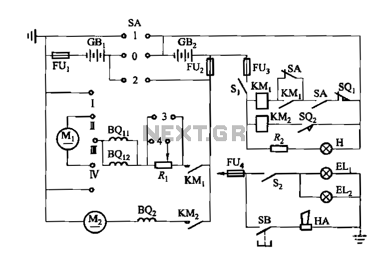
Denote cam controller SA 1 contact closure case. M1 is 1.35 kW driving motor, M2 is a 4 kW pump motor. The circuit involves a cam controller designated as SA 1, which is responsible for managing the operation of...
An electromagnetic vibration table or feeder is designed to move small objects along a specific track or cylindrical path through forced vibrations. This device can be custom-built to facilitate the movement of items along a rail tube. The vibration...
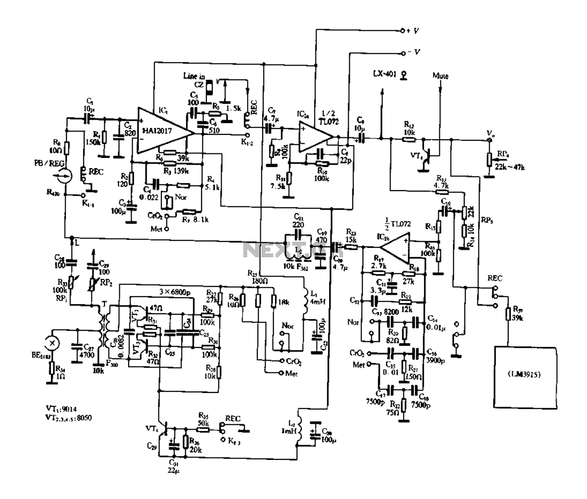
Figure 3-17 illustrates a pre-equalizer amplifier with sound recording capabilities, featuring the following characteristics: (1) The circuit does not utilize a conventional mechanical switch circuit; instead, it employs fully enclosed electromagnetic relays. This design allows for a core and...