
Overspeed indicator
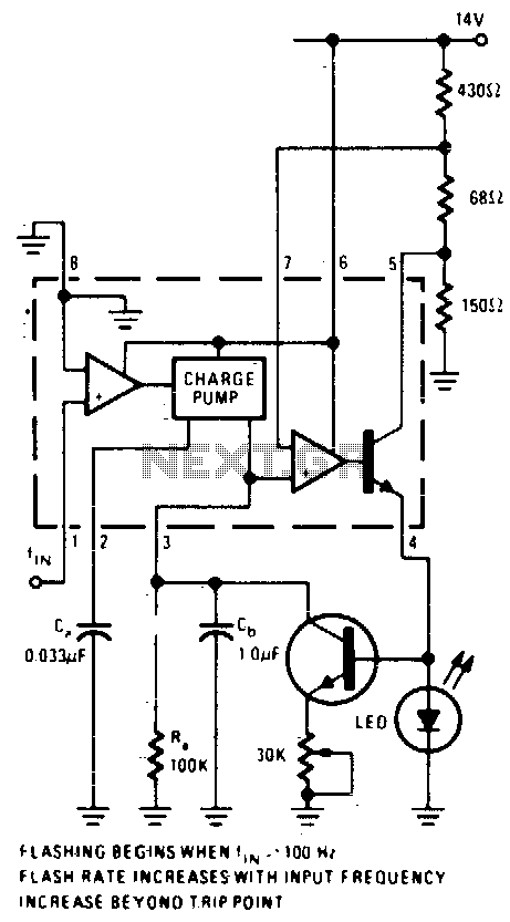
The described circuit employs an operational amplifier configured as a comparator to monitor the output voltage from a converter. The comparator's non-inverting input is connected to a reference DC voltage, while the inverting input receives the output signal from the converter. When the frequency of the input signal exceeds the predetermined threshold of 100 Hz, the comparator output transitions, signaling the LED to illuminate.
In this design, the LM2907 or LM2917 integrated circuits serve as the core components. The LM2907 is a frequency-to-voltage converter that can effectively interpret varying input frequencies, while the LM2917 is a similar device with enhanced features for frequency detection and conversion. The choice of IC depends on the specific requirements of the application, such as response time and output characteristics.
The capacitor C2 plays a crucial role in determining the LED flashing rate. As the frequency of the input signal increases, the average output current from terminal 3 of the comparator rises. This increase leads to a reduction in the time it takes for C2 to charge, thereby increasing the rate at which the LED flashes. This behavior can be observed in applications where visual indicators are needed to represent varying frequencies, such as in audio signal processing or frequency modulation systems.
To ensure reliable operation, proper power supply decoupling and biasing of the op-amp are essential. Additionally, the circuit may include resistors to limit current through the LED and to set the gain of the comparator. Overall, this op-amp comparator circuit provides a straightforward solution for frequency detection and visual indication through LED flashing, making it suitable for various electronic applications.An op-amp comparator is used to compare the converter output with a dc threshold voltage. The circuit flashes the LED when the input frequency exceeds 100 Hz. Increases in frequency raise the average current out of terminal 3 so that frequencies above 100 Hz reduce the charge time of C2, increasing the LED flashing rate IC = LM2907 or LM2917. 🔗 External reference
Related Circuits
The circuit indicates two different water temperature trip points by activating LEDs when the specified temperatures are reached. It is built around the LM2904 dual operational amplifier, which is powered by a 12 V automotive system. A thermistor is...
With this circuit can determine whether any of the phones of the same line is busy (it's up the handset), with the help of a LED. The circuit has no measurable effect on the telephone, so that there are...
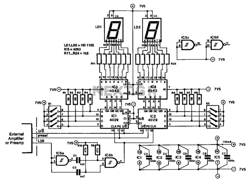
The indicator is designed for use with an audio amplifier or preamplifier, but it can also be utilized in other applications requiring rapid counting of steps or changes. To avoid interference with the audio signal, the circuit operates in...
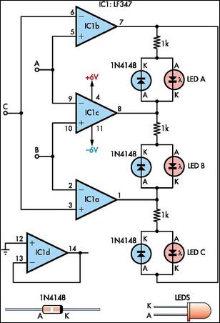
This circuit indicates which of three voltages, ranging from approximately -4V to +4V at points A, B, and C, is the highest by illuminating one of three indicator LEDs. It can also be configured to indicate the lowest of...
A UHF indicator, or wavemeter, is a device that measures frequencies and determines the resonance frequency of an LC circuit. This device operates without the need for radiation. The oscillator is constructed using transistors T1 and T2 (two BF494),...
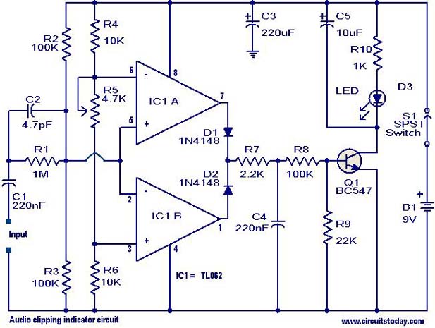
This circuit is designed to detect clipping in a specific waveform. Clipping occurs when the amplitude of a waveform decreases before reaching its expected limit. The circuit activates an LED as an indication that the tested signal is experiencing...
Warning: include(partials/cookie-banner.php): Failed to open stream: Permission denied in /var/www/html/nextgr/view-circuit.php on line 713
Warning: include(): Failed opening 'partials/cookie-banner.php' for inclusion (include_path='.:/usr/share/php') in /var/www/html/nextgr/view-circuit.php on line 713