
pic circuit

The 50 MHz auto-ranging frequency meter is designed to provide an efficient and user-friendly means of measuring frequency signals across a wide range. The core component, the PIC 16C84 microcontroller, is a versatile 8-bit device that enables precise frequency measurement and control of the display outputs. The system's architecture integrates four seven-segment displays, which are driven by the microcontroller to present frequency readings in an exponential format. This format is advantageous for displaying a wide range of values while ensuring that significant digits are preserved, enhancing the accuracy of readings.
The frequency meter operates by sampling the input signal and processing the frequency data using the microcontroller's internal algorithms. The shutdown feature is particularly useful for power conservation, allowing the device to remain inactive during periods of no signal input. Upon detecting a frequency input, the microcontroller is programmed to wake from its low-power state, ensuring quick responsiveness for real-time measurements.
In addition to the frequency meter, the cable tester module serves a distinct purpose by allowing users to verify the integrity of various types of cables over long distances. The design consists of two separate modules that communicate with each other, enabling the user to test cables such as network and telephone lines effectively. This module also incorporates a microcontroller and displays to provide feedback on the testing process.
Complete schematics for both the frequency meter and the cable tester are provided, along with the necessary source code for implementation. The assembly of the software is facilitated by Timo Rossi's picasm, which is a suitable assembler for the PIC microcontroller environment. The documentation accompanying these projects offers guidance on assembly, operation, and troubleshooting, making it accessible for educational purposes and practical applications in electronics testing.This is a simple 50 MHz auto-ranging Frequency meter, developed as a course project by Simone Benvenuti and Andrea Geniola. It uses a single PIC 16C84 and 4 displays to measure frequencies in the 0Hz. 50MHz range. Output is shown in exponential format (XXX E) in order to have enough significant digits. The PIC shuts down when the input is idle for some time, and turns on automatically when a frequency is applied to the input. Source code and schematics available. This is a cable tester made of two modules, useful to test network or phone or other cables where the two ends are far away from each other. Partly developed as a course project by Maurizio Fabbri, Fabio Raso. Schematics and full source and documentation. The sources should be assembled with Timo Rossi`s picasm. 🔗 External reference
Related Circuits

A nightlight combined with a wake-up alarm has been developed. This nightlight incorporates six LEDs that activate when a photosensor detects low ambient light levels. Additionally, a buzzer plays a cheerful tune when ambient light levels increase again. The...
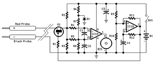
Short circuits or broken PCB tracks can be easily identified using a multimeter; however, this tool may yield inaccurate results when testing the efficiency of a transistor or diode unless the component is unsoldered and removed from the PCB....
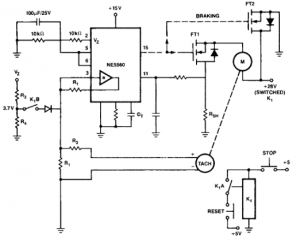
This circuit is useful for creating a constant speed motor control, ensuring that the motor speed remains constant despite variations in load and electrical voltage. The circuit for a constant speed motor control typically employs feedback mechanisms to maintain a...
A fluorescent tube is connected in an LC resonant circuit consisting of inductor L2 and capacitor C9. The bidirectional breakdown diode VD4 initiates the starting circuit. When AC power is applied, the gate potential of transistor VT2 increases due...
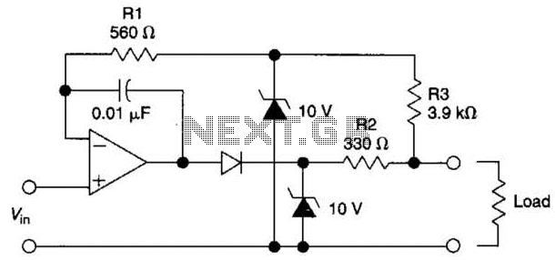
The circuit is designed to drive an external load. A fault condition in the external load circuit could feed excessive current or voltage back into the line drive circuit. If excessive voltage appears from the load, the two zener...

The circuit illustrated in Figure 3-132 represents an automatic round-trip plug braking circuit. To prevent or limit malfunctions of switch SQ1 and switch SQ2 that could lead to accidents, two additional protection limit switches, S03 and S04, have been...