
Piezoelectric alarm rings clear as a bell

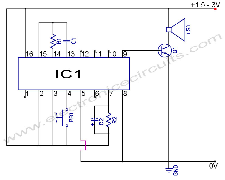
The circuit utilizes the 555 timer in an astable mode to generate a square wave output that controls the operation of the piezoelectric alarm. The timer's configuration allows for continuous oscillation, creating a rhythmic sound output. The low time (6.93 ms) corresponds to the duration of the initial bell strike, while the high time (236 ms) dictates how long the bell tone is sustained before it begins to decay.
The transistor switch (Q1) plays a crucial role in controlling the alarm. When the 555 timer outputs a low signal, Q1 is turned on, allowing current to flow through the piezoelectric alarm, producing sound. The charging of capacitor C3 during this phase helps ensure that the alarm is energized adequately. Upon transitioning to a high output from the timer, Q1 is turned off, which stops current flow to the alarm and allows the sound to decay as C3 discharges.
The timing components R1, R2, and C1 can be selected based on the desired sound characteristics. For instance, increasing R1 or R2 will extend the duration of the high time, resulting in a longer sustain phase. Alternatively, adjusting C1 will influence both the strike and sustain times. Capacitor C3's value can also be modified to create different decay rates for the sound output, allowing for customization of the alarm's auditory profile.
This circuit design is straightforward, cost-effective, and adaptable, making it suitable for various applications where a less abrasive sound output is preferred.A common piezoelectric alarm, such as the Murata (Smyrna, GA) PKB5-3A shown, has many valuable attributes. It is compact, lightweight, efficient and reliable. However, the loud, high-pitched sound output can be quite irritating in many applications. The simple and inexpensive circuit provided here transforms this obnoxious little buzzer into a ple asantsounding bell ( see the figure ). At the heart of the circuit is the popular 555 timer U1, which is configured as an astable multivibrator. The output low time is a short pulse that initiates the bell strike. The strike time is 0. 693 †” R2 †” C1. For the component values shown, the strike time is 6. 93 ms. The output high time is the sustain time during which the amplitude of the bell tone decays continuously.
The high time is 0. 693 †” (R1 + R2) †” (C1). For this circuit, the high time is 236 ms. When the output of U1 is low, the series transistor switch Q1 turns on through bias resistor R3 to energize the piezoelectric alarm AL1 and charge capacitor C3. When the output of U1 is high, Q1 is off and the output of AL1 decays until C3 is discharged. When C3 is discharged again, the cycle is repeated. The values of timing components R1, R2, and C1, along with decay capacitor C3, aren`t critical; various sound effects can be produced by experimenting with them.
🔗 External reference
Related Circuits
Touch the sensor of the alarm with your finger, and it starts beeping. It continues for a period and then stops. Touching it again will activate the beeping once more. This description outlines a basic touch-activated alarm system. The...
Musical Doorbell Circuit Diagram. This musical doorbell circuit utilizes the UM3481 A series integrated circuit (IC). It is designed for applications including toys and doorbells. The musical doorbell circuit leverages the capabilities of the UM3481 A series IC, which is...
A simple light fence security beeper is presented. This circuit can function as a door alarm, gate alarm, pathway alarm, etc. It can be powered by any 12 Volt DC power supply. The operation of this circuit is straightforward....
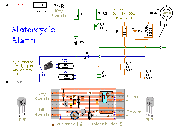
The circuit board and switches must be protected from the elements. Dampness or condensation will cause malfunction. Without its terminal blocks, the board is small. Ideally, you should try to find a siren with enough spare space inside to...
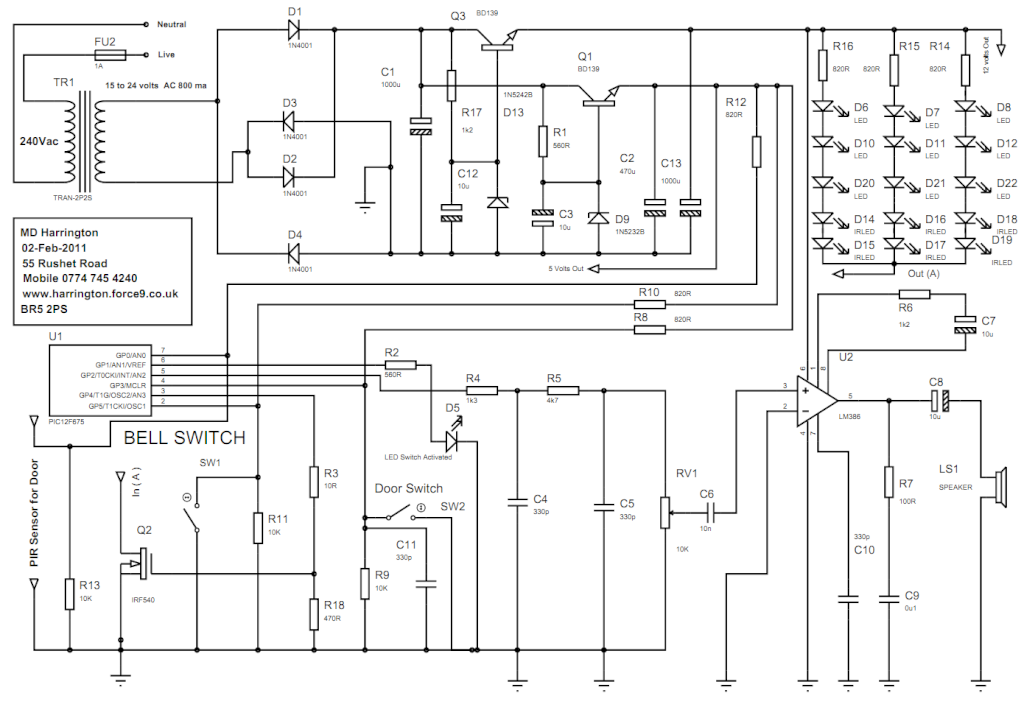
The circuit consists of a power supply formed by TR1, Q3, D13, Q1, and D9. This power supply provides both the 12-volt and 5-volt rails required for the microcontroller. The power supply circuit is essential for ensuring stable voltage levels...

This circuit is capable of generating up to 1 W of audio power to drive a speaker or horn. When the CDS cell is exposed to light, its resistance decreases, activating NOR gate (a). This activation causes gates (a)...