
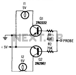
Rf probe for vom

The RF voltage probe is designed to facilitate accurate measurements of radio frequency voltages, particularly in applications where high-frequency signals need to be assessed. The probe's compatibility with a multimeter that has a high input impedance of 20,000 ohms per volt ensures minimal loading on the circuit under test, thereby preserving the integrity of the measurement.
The core component of this probe is the 1N4149 diode, which serves as a protective element. Its breakdown voltage of approximately 100 V is a critical specification, as exceeding this limit could lead to diode failure and inaccurate readings. Therefore, it is essential to ensure that the RF voltages being measured do not surpass this threshold to maintain the functionality and reliability of the probe.
In practical applications, this probe can be utilized in various fields, including telecommunications, electronics testing, and RF circuit design. Users should connect the probe to the RF source and the multimeter, ensuring proper calibration to achieve accurate voltage readings. The frequency range of up to 200 MHz allows for versatility in measuring different RF signals, making this probe an invaluable tool for engineers and technicians working with high-frequency electronic systems.
Overall, this RF voltage probe is an essential instrument for precise measurements in high-frequency applications, providing both reliability and ease of use when interfacing with standard multimeters.This probe makes possible relative measurements of rf voltages to 200 MHz on a 20,000 ohms-per-volt multimeter Rf voltage must not exceed the breakdown rating of the 1N4149—approximately 100 V.
Related Circuits
This logic probe utilizes a single CMOS integrated circuit (IC) to indicate three logic states: High, Low, and Pulsing. If the probe input is in a high impedance state, which occurs when it is not connected to a circuit,...
When testing circuits with a logic probe, it is sometimes difficult to watch the LEDs on the probe to determine the logic state. With this probe, the logic states are audible. This probe is designed for TTL circuits only...
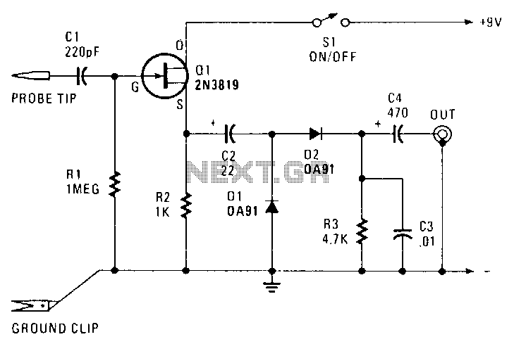
The transistor Q1 is configured as a source-follower buffer stage, providing slightly less than unity voltage gain. This configuration results in a high-impedance input of approximately 1 MΩ, shunted by about 10 pF, which minimizes loading on the equipment...
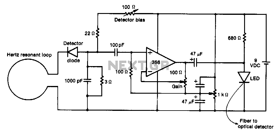
This RF probe is coupled with a fiber-optic connection to the test equipment. It utilizes inexpensive components to enhance probe performance at UHF frequencies. The receiving antenna in this probe feeds an envelope-detector diode. After amplification by the LF356...
By connecting this circuit to a powered logic device, an indication of its status can be obtained. If the circuit is open, neither of the test lamps will illuminate. If the circuit is grounded, the low (or zero) lamp...
This tester is designed to locate stray electromagnetic (EM) fields. It can easily detect both audio and RF signals up to frequencies of around 100 kHz. However, this circuit is not a metal detector; it will detect metal wiring...