
Signal Clamper Using Diode

In an electronic circuit, clamping is a technique used to restrict the voltage of a signal to a specified range. The combination of a diode and a capacitor is a common method for achieving this. In this configuration, the diode allows current to pass in one direction only, effectively blocking negative voltage excursions of the AC signal. The capacitor, connected in parallel with the load, serves to smooth out the voltage variations, providing a more stable output.
When an AC signal is applied to the circuit, the diode becomes forward-biased during the positive half-cycles, allowing the current to flow and charging the capacitor. As the AC signal transitions to the negative half-cycle, the diode becomes reverse-biased, preventing current flow and thus clamping the output voltage to a level determined by the capacitor's charge. This results in a waveform that is shifted entirely into the positive voltage region.
The capacitor's value is critical in determining the response time of the clamping circuit. A larger capacitance will result in a slower response time, leading to a more stable output but potentially less responsiveness to rapid changes in the input signal. Conversely, a smaller capacitance will allow for a quicker response but may result in a less stable output.
This clamping circuit is widely used in applications where it is essential to maintain a positive voltage level, such as in signal conditioning for analog-to-digital converters, preventing negative voltage spikes that could damage sensitive components, or in audio processing to ensure that audio signals remain within a desired range. Proper selection of the diode and capacitor components, along with consideration of the input signal characteristics, is essential for optimal performance of the clamping circuit.Diode and capacitor can be used to clamp an AC signal, shift the level into positive region for all cycle. Sometimes this condition is needed, to have positive.. 🔗 External reference
Related Circuits
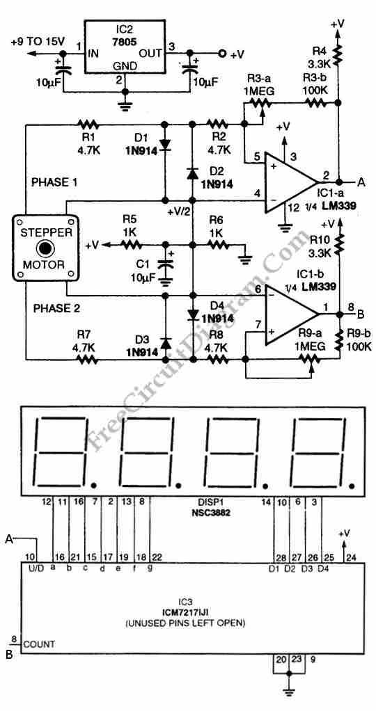
The circuit illustrated in the schematic diagram below allows for the visualization of the direction and shaft rotation of a stepper motor on an LED display. Instead of employing a digital rotation encoder as an input, this circuit utilizes...
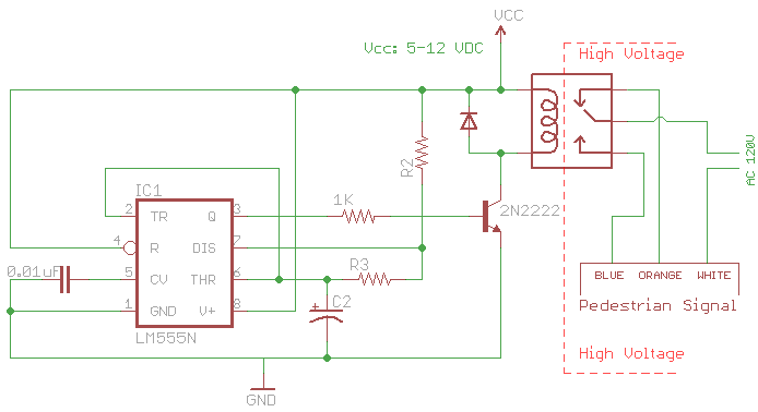
The signal consists of three wires: common, "walk," and "don't walk." This document outlines the operation of the unit's countdown feature. The information and examples provided here are applicable to other models and brands of signals. The signal was...
This project measures the clock pulses supplied to the Timer input of the AVR microcontroller. The Bascom code counts the clock pulses over a duration of 1 second and displays the result. The circuit for this project primarily consists of...
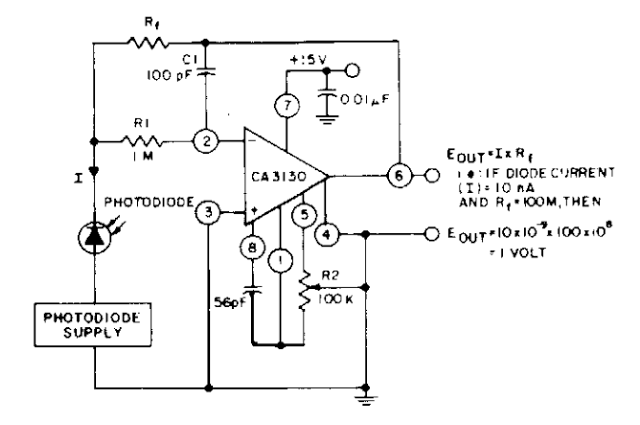
The photodiode current-to-voltage converter circuit employs three CA3130 BiMOS operational amplifiers, designed for applications that require sensitivity to sub-picoampere input currents. This circuit generates a ground-referenced output voltage that is directly proportional to the input current flowing through the...
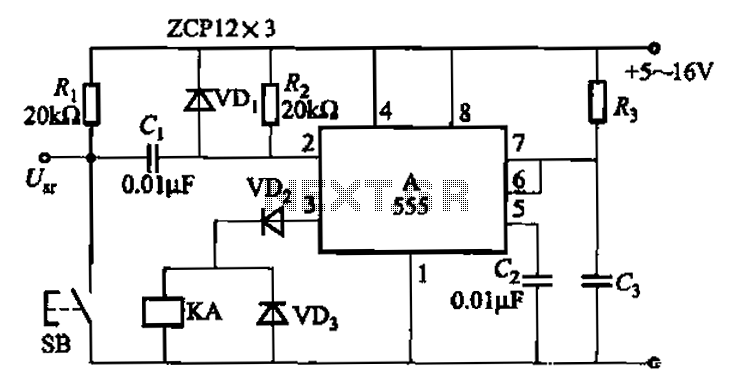
The 555 integrated circuit is utilized in a delay circuit configuration, functioning as a one-shot timer. The delay time can be adjusted using resistor R3 and capacitor C3. Typical values for R3 range from 1 kΩ to 10 MΩ,...
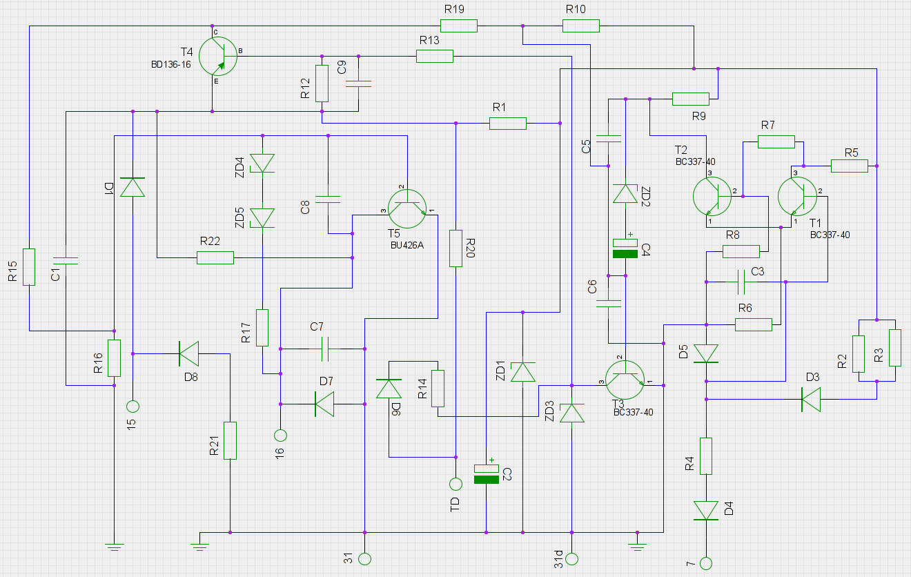
An old ignition module from a 1978 W116 model Mercedes-Benz is being reverse-engineered. The original circuit diagram is not available, so a new one has been created based on the printed circuit board (PCB). The circuit has been assessed...