
Simple power Supply for LEDS

Where "C" is in µF and "I" is in milliamperes. A design current of 10 mA per LED was selected. Thus, for ten LEDs, 100 mA is the total current. Inserting this current value into the formula yields a capacitor value of 3.1 µF. To achieve this value, two capacitors connected in parallel were used. Recall that the total capacitance of capacitors connected in parallel is simply the arithmetic sum of the individual capacitors.
The circuit design involves using a capacitor as a voltage-dropping component to power a series of ten LEDs. Each LED requires approximately 10 mA, leading to a total current requirement of 100 mA for the entire array. The primary advantage of using a capacitor in this application is the efficiency in terms of power loss, as capacitors exhibit negligible power dissipation compared to resistors.
In the schematic, the AC line voltage of 117 V is connected to the capacitor, which is selected based on the empirical formula provided. The formula indicates that for a current of 100 mA, a capacitor value of 3.1 µF is required. To achieve this capacitance, two capacitors can be connected in parallel, with each capacitor's value contributing to the total capacitance. For instance, using two capacitors of 1.55 µF each will yield the desired total capacitance of 3.1 µF.
The output from the capacitor is then connected to the LED array, ensuring that the voltage is reduced to a safe level for the LEDs to operate effectively. The design should also incorporate a rectifier, if necessary, to convert the AC voltage to DC, as LEDs typically require direct current for optimal performance.
In summary, this circuit design effectively demonstrates a practical application of capacitive voltage dropping for LED lighting, showcasing the balance between simplicity, cost-effectiveness, and efficiency in electronic circuit design.LED's are great display tools. Their prices have decreased to a point where they are replacing more conventional light sources. In one sense their characteristic need for low voltages is an advantage e.g compatibility with I.C drives, but this voltage requirement can also be a disadvantage. I wanted to light some LED's in a simple sign application, nothing fancy, but I needed to decrease the utility line voltage to a LED-compatible value for this application.
The line voltage can be reduced in various ways, via dropping resistor, a transformer, a "brick" power supply, a capacitor etc. A dropping resistor wastes considerable power and generates heat. A "brick" power supply must be adapted to the particular design needs, i.e a specific voltage and current and also may have an expense associated with it that is undesirable for a simple circuit.
A transformer can be bulky, weigh a lot and may be expensive. capacitor can act as a voltage dropping component and in this instance, was chosen to light the static LED display shown below. The considerable drop in voltage from the line (117 v.a.c) down to approximately 2-1/2 volts a.c results in an almost negligible power loss in the capacitor(s).
It is simple, low cost and small. The capacitor value may be computed via the following empirical formula. This formula is valid for the circuit shown in Fig.2: Where "C" is in uFd and "I" is in miliamperes. A design current of 10 mA per LED was selected. Thus for ten LED's, 100mA is the total current. Inserting this current value into the formula, yields a capacitor value of 3.1uFd. To achieve this value, two capacitors connected in parallel were used. Recall that the total capacitance of capacitors connected in parallel is simply the arithmetic sum of the individual capacitors:
🔗 External reference
Related Circuits
By combining a current-reuse amplifier and a switch-based mixer, a dual-band receiver front end offers excellent performance with extremely low power consumption. The dual-band receiver front end integrates a current-reuse amplifier and a switch-based mixer to achieve high performance while...
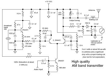
In many discussions of LPAM transmitter design, references to "the Wenzel circuit" or "the Wenzel transmitter" are common. These terms refer to a clever transmitter design that became popular in the mid-1990s and early 2000s for those interested in...
This is a simple circuit that does the day/night switchings you have in mind. POT1 is used to set the light level at which the circuit switches from enable to disable. The described circuit functions as an automatic day/night switch,...

The circuit is constructed using two 555 timer integrated circuits (ICs), designated as U1 and U2. U1 is configured as a variable duty cycle oscillator with a fixed time period of approximately 0.1 seconds. The duty cycle can be...
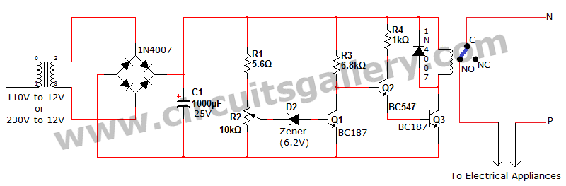
Voltage fluctuation is a significant concern in residential settings. For various reasons, the supply voltage may exceed 110V or 230V. This excessive voltage can potentially damage household electrical devices. An effective solution for electrical protection is the implementation of...
Probably the easiest way of doing automatic switch off is with relay logic. In the diagram, the box marked RL1 is the coil, the 2 in the coil box tells you there are two sets of contacts somewhere on...