
Simple Transistor Tester

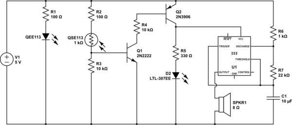
The circuit described is a high-gain amplifier configured to produce a flashing LED output based on the feedback loop established by the components involved. The key components include a high-gain amplifier, an LED, a capacitor (10 µF), and a resistor (330 kΩ). The flashing rate of the LED is influenced by the time constant created by the capacitor and resistor, which determines the charge and discharge cycles of the capacitor.
In this circuit, the high-gain amplifier is typically implemented using a transistor or an operational amplifier. The feedback mechanism allows for oscillation, which results in the LED flashing. The specific choice of the capacitor (10 µF) and the resistor (330 kΩ) will dictate the frequency of the oscillation, with the formula for the time period (T) being approximately T = R × C, where R is the resistance in ohms and C is the capacitance in farads.
The operation of the circuit can be altered by removing one of the transistors and replacing it with an unknown NPN transistor. The orientation of the transistor pins must match the configuration shown in the reference photo to ensure proper functionality. When correctly installed, the NPN transistor will allow the circuit to operate, causing the LED to flash as intended.
To deactivate the circuit, one of the transistors can be removed, which interrupts the feedback loop and stops the oscillation, effectively turning off the LED. This circuit can be used in various applications where a visual indicator is needed, such as in timers, alarms, or decorative lighting systems. Proper consideration should be given to the power supply voltage and current ratings to prevent damage to components.This is basically a high gain amplifier with feedback that causes the LED to flash at a rate determined by the 10u and 330k resistor. Remove one of the transistors and insert the unknown transistor. When it is NPN with the pins as shown in the photo, the LED will flash. To turn the unit off, remove one of the transistors. 🔗 External reference
Related Circuits
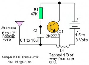
This is likely the simplest radio transmitter available, consisting of five components and capable of being assembled in a compact space. It is suitable for science fair projects or other science-related endeavors where short-range transmission is beneficial. The device...

Two headlight reminder circuits are designed for easy installation and operation based on the KISS (Keep It Simple Stupid) principle. The basic circuit consists of a 12V piezo buzzer connected between the lights circuit and a door switch. The...
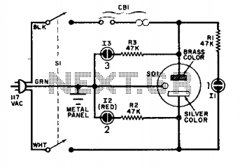
The circuit is straightforward and reliable when connected properly. Under standard operating conditions, only lamps 1 and 3 should illuminate. If lamp 2 activates, it indicates that the cold lead is at 117 volts above ground. The described circuit operates...

The circuit presented here is a powerful AM transmitter utilizing a ceramic resonator/filter operating at 3.587 MHz. This circuit primarily relies on a transistor for its core functionality. It is possible to use resonators/filters of other frequencies, such as...

This figure illustrates the schematic diagram of a simple inductance meter. U1 is a 74LS00 two-input quad NAND gate logic integrated circuit. Two resistors, a capacitor, and a surplus microprocessor crystal create a stable crystal oscillator operating close to...
This circuit detects when a tube is empty and pulses a piezo buzzer at 5-second intervals. It is currently operational with a 5V supply on a breadboard but needs to be adapted for a 12V supply from a wall...