
Single phase half-wave phase-shift trigger circuit resistance-capacitance

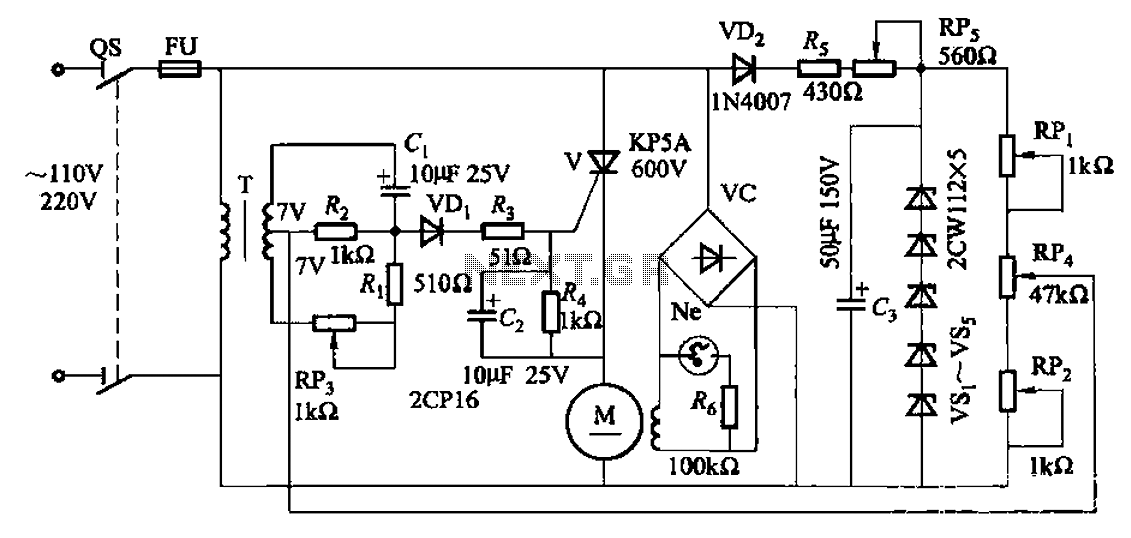
The circuit under discussion utilizes a phase shift bridge configuration, where the output voltage can be finely tuned via a potentiometer (RP). This adjustment directly influences the performance of the rectifier load (Rfz), thereby allowing for precise control over the power delivered to the load. The phase shift bridge operates by manipulating the phase relationship between the input and output signals, enabling effective voltage regulation.
In the circuit, the current limiting resistor (R) plays a crucial role in safeguarding the thyristor gate by restricting the amount of current flowing into it. This is essential for preventing damage to the thyristor, which can occur due to excessive gate current. The design ensures that the thyristor operates within its safe limits, enhancing the reliability and longevity of the circuit.
Additionally, the inclusion of diodes (VDi and VDz) serves as protective elements against reverse voltage spikes. These diodes are configured to prevent breakdown of the control gate by shunting any excessive reverse voltage away from the sensitive components. This protection is vital in circuits where inductive loads may generate back EMF or where transients can occur, ensuring stable operation and preventing circuit failure.
The waveforms depicted in FIG. 16-1 (b) further illustrate the operational characteristics of the circuit at various points, providing insight into the dynamic response of the system as the potentiometer is adjusted. This visual representation aids in understanding the relationship between the input adjustments and the resultant output behavior, making it easier to analyze and optimize the circuit performance.Adjusting potentiometer RP, the output voltage of the phase shift bridge diagonal oD phase change accordingly, thus obtained Rfz rectifier load power is also changed accordingl y. Waveforms at respective points in FIG. 16-1 (b) shown in the figure, R is the current limiting resistor to limit the thyristor gate current V; diode VDi, VDz to protect the control -gate from excessive reverse voltage breakdown.
Related Circuits
The ultimate source of energy is the Sun. It is possible to generate current from sunlight using solar panels. These panels convert light energy into electrical energy. A solar panel consists of a number of solar cells, which produce...
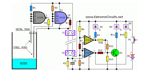
Simple two-wire remote monitoring unit with a three-LED level display, powered by a 9V battery. The entire project was developed at the request of a friend. The remote monitoring unit is designed to provide a straightforward solution for level indication...
A 35W resistive and capacitive half-wave phase-shift trigger control circuit is designed for automatic or semi-automatic welding equipment to manage wire feeding and welding carriage travel. This system necessitates a drive control circuit to fulfill the welding process requirements....
A small delay circuit is required to produce a pulse for a cell phone vibrational motor every 0.75 seconds, with an adjustable delay time ranging from 4 to 10 seconds. The circuit will be powered by a 9-volt battery. To...
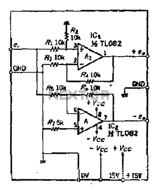
A balanced output is often associated with the positive phase amplifier output terminal of an operational amplifier, which is typically viewed as the inverting amplifier circuit. However, the reversed phase output can lead to a loss of balance in...
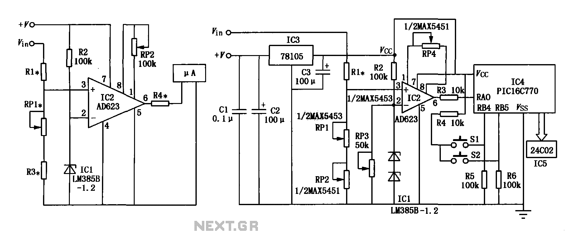
The range precision voltmeter electrical schematic is depicted in Figure (a) below. It features an amplifier circuit and several high-precision components that significantly enhance the performance range of the voltmeter. The inverting input of the instrumentation amplifier AD623 (IC2)...