
Stereo Audio Power Meter

The audio power metering circuit operates by monitoring the output power of an amplifier and ensuring that the connected speaker does not exceed its power rating. The inclusion of relay RY1 acts as a protective mechanism, disconnecting the speaker when the power output surpasses safe levels. The circuit is capable of handling stereo applications by utilizing two channels, allowing for simultaneous monitoring of both left and right audio outputs.
The attenuator formed by resistors R1, R2, and R3 reduces the signal level to a manageable range for the subsequent components. Capacitor C1 plays a crucial role in voltage detection; it stores charge and allows the comparator IC3A to respond to the voltage level that indicates a potential overload. When the voltage across C1 reaches a predetermined level, IC3A outputs a high signal, which activates the drive circuit composed of IC4 and Q4. This stage amplifies the signal to trigger transistor Q3, which operates relay RY1.
The illumination of LED21 serves as a visual indicator of the relay's activation, providing immediate feedback that the speakers have been disconnected due to excess power. Meanwhile, IC1 continuously monitors the voltage across C1 and drives a bar-graph display consisting of ten LEDs (LED1 to LED10). This visual representation allows users to easily gauge the power output level, enhancing usability and providing clear feedback on the amplifier's performance.
For applications requiring a maximum power measurement of 50W into a 2-ohm load, the circuit design specifies replacing resistors R1 and R7 with a wire. This modification ensures that the signal path is optimized for higher power levels, allowing for accurate readings without attenuation. Overall, this circuit is a robust solution for monitoring audio power output, protecting speakers, and providing visual feedback to users. This circuit is used to meter the audio power output of an amplifier feeding a speaker. RY1 is actuated if excess power is fed to the speaker. Two channels are included for stereo applications. R1 and R2 and R3 form an attenuator. When a signal level is reached that produces a voltage across CI, comparator IC3A goes high, and IC4 and Q4 produce enough drive to Q3 to trip relay 1, which cuts off the speakers. LED21 will light as well. In addition, IC1 reads the voltage across CI. IC1 is a bar-graph driver, which lights bar-graph display LED1 through LED10. To read a maximum power level of 50W into 2ohm, R1 and R7 should be replaced by a piece of wire between the appropriate printed circuit board pads.
Related Circuits
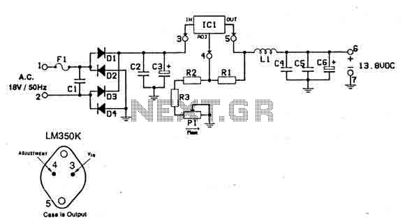
This power supply is designed for use with RF equipment such as linear amplifiers, transmitters, receivers, and any application that requires a clean and noise-free signal. The circuit is straightforward and can be powered using a 220V/18V/3A transformer connected...
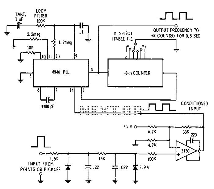
Automotive engine pulse points or other sensors are filtered using the transmission device 3130 CMOS operational amplifier, which functions as a comparator to fulfill the input conditions. The pulse subsequently flows into a 4046 phase-locked loop (PLL) N-counter, which...
Make your own solar powered robot at home using things you probably already have. Transistors, resistor, capacitor, solar battery and flashing LED are available at any electronic store, if you don't already have them. Solar cells out of calculators...
The following circuit diagram illustrates a simplified application circuit for the TDA8932B/33(B) device when it is powered by an asymmetrical supply (single supply). The TDA8932B/33(B) is a class-D audio amplifier integrated circuit designed for efficient audio amplification in various applications....
The soft start circuit refers to a power circuit where the output voltage gradually increases to a specified value, thereby protecting the load circuit from unwanted voltage surges. It can output a voltage of 24V and a current of...
Typically, most Japanese motorcycles do not have a charge control lamp at all, and even on bikes equipped with such a lamp (like the Bosch system used in BMW and Moto Guzzi), defects may still occur, causing the "idiot...