
STRESS METER

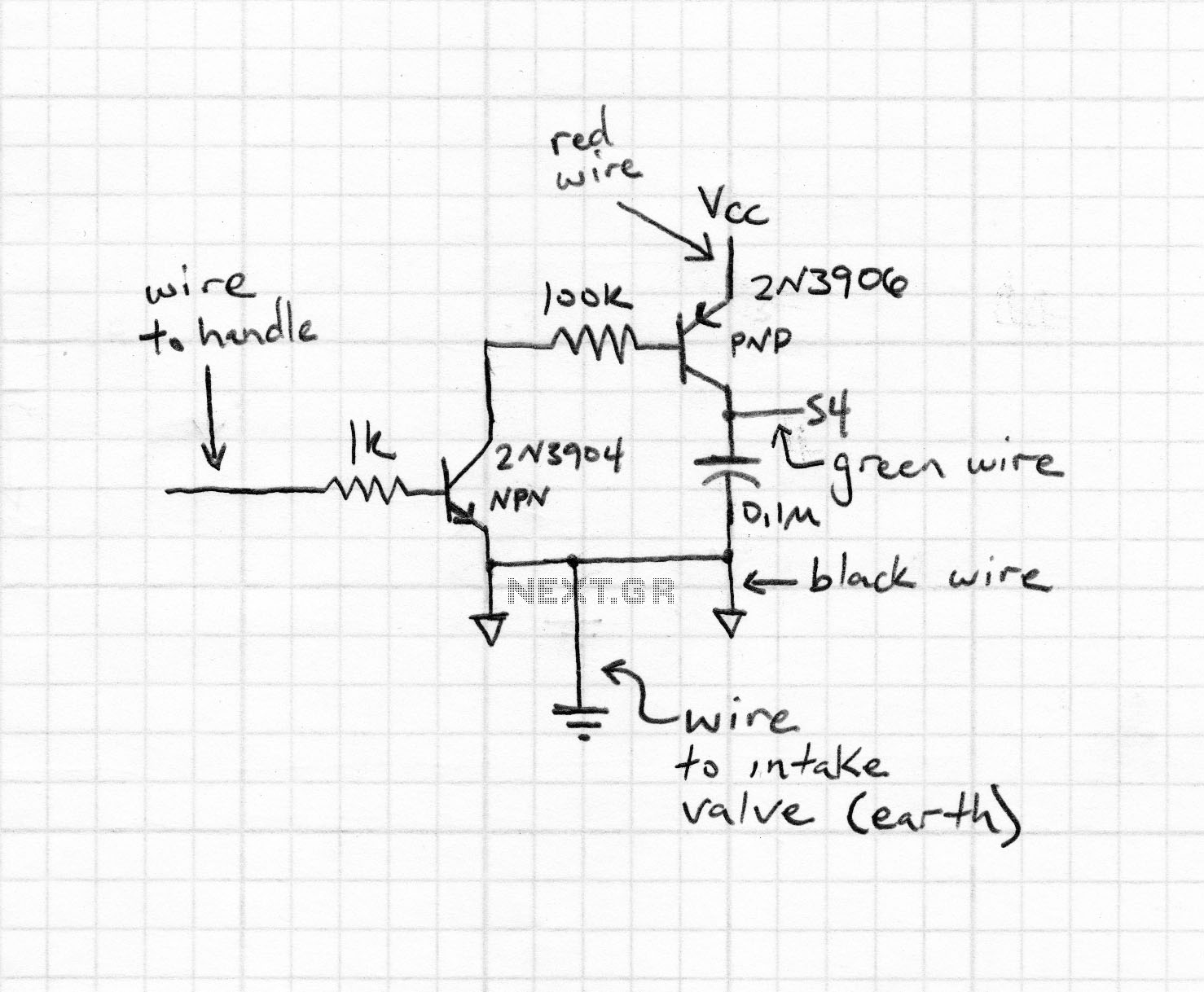
The described circuit features a circular arrangement of 16 Light Emitting Diodes (LEDs) that are controlled to create a visual chaser effect. The LEDs are likely connected in a series or parallel configuration to a microcontroller, which manages the sequencing and timing of the illumination. The circuit includes two capacitive touch pads, which serve as input devices to initiate the LED sequence. When a user touches one of the pads, the microcontroller activates the LEDs in a sequential manner, producing a chaser effect that progresses around the circle.
Each time an LED is illuminated, an audible beep is generated, likely through a piezo buzzer or a small speaker connected to the microcontroller. This auditory feedback enhances user interaction and engagement with the circuit. The microcontroller is programmed to gradually slow down the chaser effect, ultimately stopping at a random LED. This feature introduces a stress indicator element to the design, as the final illuminated LED is meant to represent the user's stress level.
The program controlling this circuit is already functional but is open to enhancements. Potential improvements could include the addition of varying chaser patterns, customizable stress indicators, or even integrating a display to provide more detailed feedback. The modular nature of the program allows for easy incorporation of new features, encouraging further development and creativity in the design process.
Overall, this circuit exemplifies an interactive and visually engaging project that combines basic electronics with programming, providing a platform for educational exploration and innovation.It consisted of 16 LEDs in a circle with two touch pads. By placing your fingers on the touch pads, the circuit started and ran the LEDs in a "chaser" pattern around the display, with a beep each time a LED was illuminated. The circuit gradually slowed down to a random LED and the display showed "how stressed you were." "What a wonderful idea for the 18 LED Display-1" I thought.
The program for this game is complete and ready to run, but it can be improved and more features can be added. This is the purpose of this article. After you see how the sub-routines are put together, you are invited to add more ideas of your own. Whe 🔗 External reference
Related Circuits
The rectifier bridge voltage is determined by the U2 element; refer to its datasheet for the maximum voltage specifications. The minimum voltage at this pin should not fall below approximately 9V, or 6.5V if low-dropout type U2 and U3...
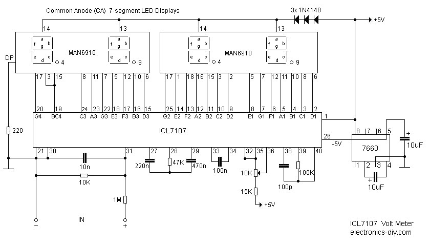
This digital voltmeter is ideal for measuring the output voltage of a DC power supply. It features a 3.5-digit LED display with a negative voltage indicator. The device measures DC voltages from 0 to 199.9V with a resolution of...
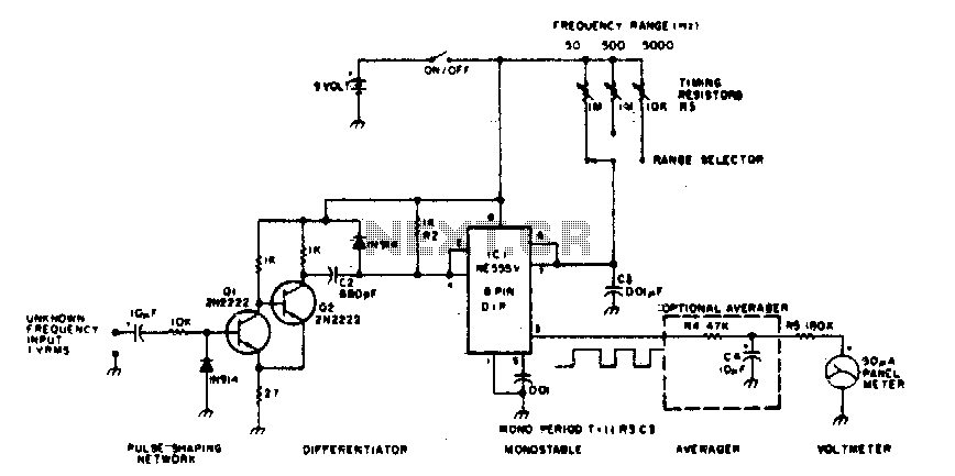
The 555 timer is utilized in a monostable multivibrator circuit that generates a pulse of fixed time width, which is activated by an unknown input frequency. The 555 timer in a monostable configuration operates by producing a single output pulse...
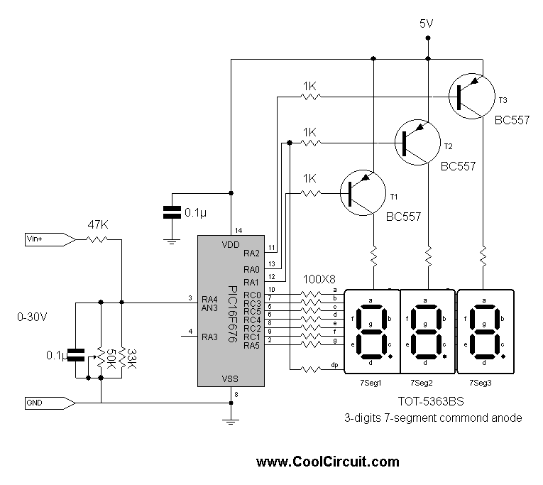
This is a simple 3-digit digital voltmeter. A PIC16F676 microcontroller is utilized to read analog signals (voltage) and display the value on a 3-digit 7-segment display. Similar principles can be applied to measure DC current using a parallel resistor...
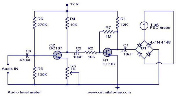
A simple audio level meter or Volume Unit (VU) level meter circuit with diagram and schematic. This sound level meter is designed using transistors with a flat frequency response in the range of 20Hz to 50kHz. The audio level meter...
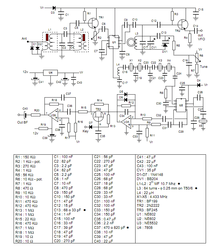
This project describes a little QRP transceiver full legal power (5 W at 12 V) for the 40 meters band. The RIG may be built in a gradual manner; in fact, it is divided into two main modules, or...