
sunrise word clock circuit design

The Sunrise Word Clock is an innovative timekeeping device that displays the time in a word format rather than traditional numerical digits. The circuit design typically involves a microcontroller, a matrix of LEDs, and a power supply.
The microcontroller serves as the brain of the clock, programmed to interpret the current time and activate the corresponding LEDs that spell out the time. For example, when the time is 2:30, the microcontroller will light up the words "It is half past two."
The LED matrix is usually constructed from a grid of individual LEDs arranged in a pattern that allows for the creation of various words. The design often employs a multiplexing technique to control the LEDs efficiently, minimizing the number of GPIO pins required from the microcontroller.
Power supply considerations are crucial for the successful operation of the clock. A stable voltage source, typically 5V, is necessary to ensure that the microcontroller and LEDs function correctly. Capacitors may be added to the circuit to smooth out any voltage fluctuations, providing reliable performance.
In the design phase, careful attention must be given to the layout of the circuit to avoid issues that were encountered in the initial breadboard version. A printed circuit board (PCB) can be designed to ensure robust connections and a compact form factor. This PCB can be created using software tools that allow for the design of circuit schematics and layout.
Overall, the Sunrise Word Clock project combines creativity with technical skills, resulting in a unique and functional timepiece that enhances any environment.Ok, I`ve finally found time to make a new post about my Sunrise Word Clock. My previous attempt at making the circuit work on breadboard didn`t go so well. I assume this is because of the poor connections that the breadboard provides and could also have been because of poor layout choices. Anyway, I`ve rebuilt.. 🔗 External reference
Related Circuits
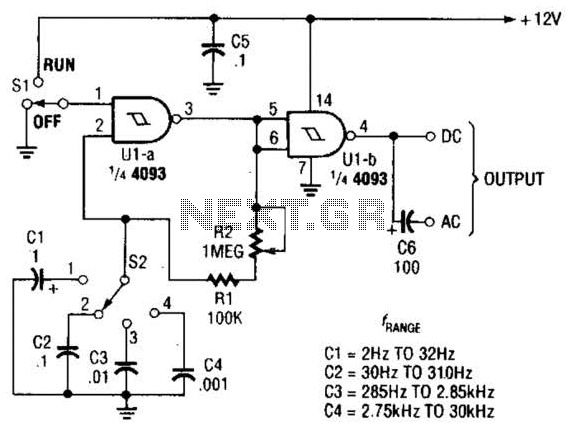
The circuit illustrated operates within a frequency range of 2 Hz to 30 kHz. Additionally, R2 is configured as either a linear or logarithmic potentiometer. The circuit is designed to accommodate a wide frequency spectrum, making it suitable for various...
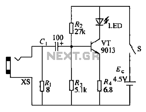
This sound frequency meter circuit is simple to build and can be constructed in a portable format. It can measure frequencies with a minimum level of 10 mV. The sound frequency meter circuit is designed to provide an effective and...
The circuit operates as a light-to-sound conversion system, featuring a light electric sound conversion circuit with two simple fiber optic connectors for experimental purposes. The electrical diagram illustrates the conversion circuit, where audio signals from a radio, music player,...

This design circuit is intended for sine wave oscillators, providing both sine and square wave outputs across a frequency range from below 20 Hz to above 20 KHz. The oscillation frequency can be easily adjusted by changing a single...
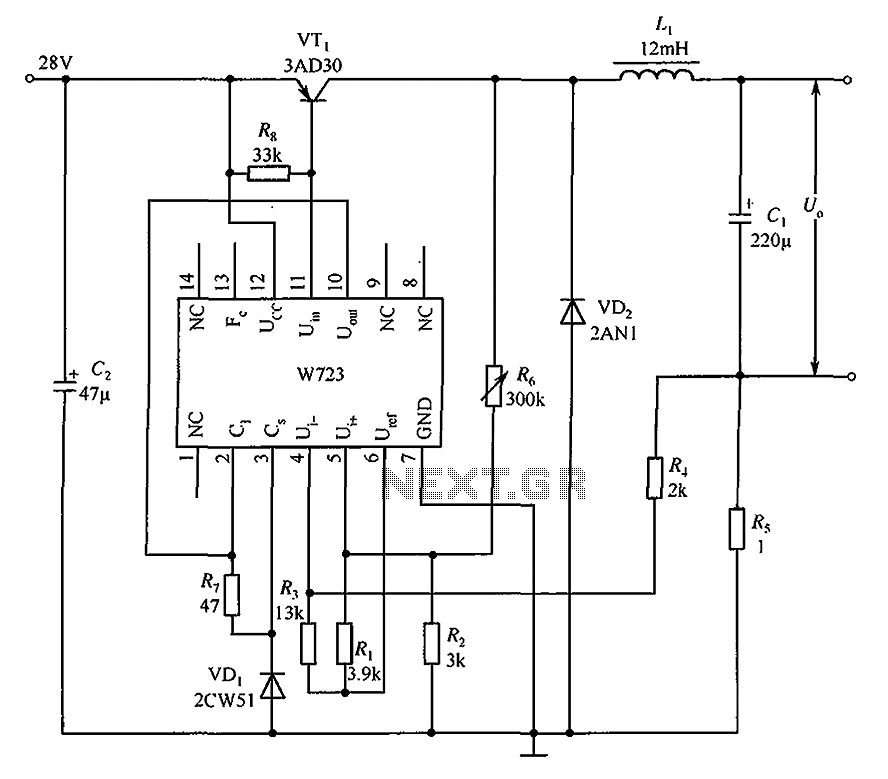
The Multiport W723 is an adjustable constant current regulator designed for use in switching regulator circuits, capable of delivering an output current of 1A. In the illustrated circuit, the W723 reference base voltage is approximately 7.2V. This voltage is...
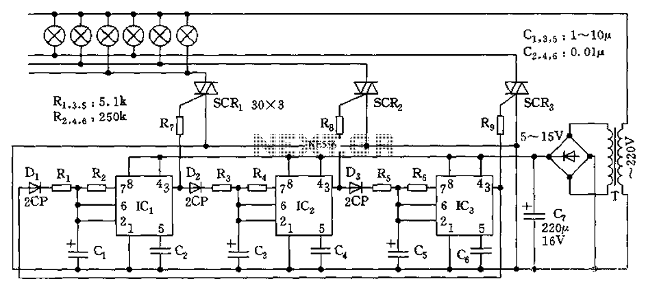
The circuit utilizes a 555 timer as its core component to control three lights through a cyclic trigger monostable delay circuit. The brightest light is controlled by a silicon-controlled rectifier (SCR) that determines the cycle of illumination. When pin...