
TX-500 500mW FM Transmitter

The first block of the TX500, based around transistor Q1 - BC549, functions as a simple modulator/oscillator. Many low-cost FM transmitters utilize similar circuits to generate radio signals, but this oscillator has been enhanced for improved stability. A notable feature is the use of a tunable coil for L1 instead of a standard air coil, allowing for precise frequency tuning, which is crucial in congested FM bands. Air coils are more challenging to tune to specific frequencies and often require more time for adjustment. The tunable coil is also more robust, reducing frequency drift caused by temperature changes. Additionally, oscillators can drift due to unstable supply voltages, whether from batteries or DC power supplies. To mitigate this issue, a 5V regulator (IC1) is employed to power the oscillator. The carrier frequency is determined by the capacitance of C4 and C5 in conjunction with the inductance of the coil L1. For tuning to the lower part of the FM band (88-100MHz), 3.5 turns and a 27pF capacitor (C5) are needed. To tune to the higher part (100-108MHz), a 10pF capacitor can be used. Capacitor C6 is essential for maintaining oscillation in Q1, while C7 aids in frequency tuning. Resistor R1, selected at 100 Ohms, ensures clear oscillation; using a lower resistance or omitting it entirely would lead to instability and the generation of unwanted frequencies. Capacitor C8 plays a crucial role in isolating the oscillator from the other blocks to prevent frequency drift, with a value of 2.2pF sufficient to transmit the oscillator's signal to the amplifier. Using a larger capacitance would not enhance the transmitter's output power and could cause undesirable behavior.
The VHF amplifier block is designed to be educational and enjoyable, particularly for those new to building amplifiers. While the schematic may appear complex due to the number of coils, they are simple to construct. An early prototype demonstrates one method for building the VHF amplifier, which minimizes external noise that could otherwise be amplified alongside the incoming signal from the oscillator. A copper PC board serves as the main board, along with small pieces for construction.The TX500 is a simple to build 500mW FM Transmitter. It consists of three blocks; modulator / oscillator, two stage 500mW VHF amplifier and LED based power meter. The TX500 allows to transmit audio signals to FM band at frequencies from 88 MHz to 108 MHz. Due to the very low power consumption of less than 100mA the circuit may be perfectly powered by using 9-12V battery or power supply if you prefer. The circuit has been divided into separate stages so that it is be better for everyone to understand how every part works independently. Notice that all of the transmitter blocks have been built using four low noise general purpose NPN transistors.
These transistors should be easy to find. Most of the regular NPN transistors should work fine and these are just some of the examples: BC549 (low noise), 2n2222, BC109 (low noise), BC107, etc. Please be aware that audio power transistors like BD140, 2n3055, TIP3055, 2SC5200 and such will not work because they can not handle higher frequencies.
Thanks to the fact that the regular NPN can work at 100MHz and above we can use them in all of the lower power blocks of FM transmitters. If you prefer you may also use RF transistors like BF199, MPSH10, BF240, etc. The first block of TX500 based around transistor Q1 - BC549 acts as a simple modulator / oscillator. Many of the low cost FM transmitters use very similar circuit to generate radio signals but this oscillator has been carefully improved to provide much better stability.
First thing that does make a great difference is the use of a tunable coil for L1 as opposed to a regular air coil. The use of this kind of coil allows for precise tuning of a desired frequency which is especially important on crowded FM bands.
An issue with an air based coils is that it is much more difficult to tune-in to a specific frequency and usually more time is needed to set such oscillator to a desired frequency. Another advantage of tunable coil is that its coil is very firm and thus much more resistive to frequency drifts caused by an temperature changes.
These type of oscillators are also prone to frequency drifts caused by unstable supply voltages. This refers both to a batteries and DC power supplies as well. To help solve this problem an IC1 - 5V regulator is used to power an oscillator. The carrier frequency of an oscillator is determined by the capacity of C4, C5 in conjunction with the inductance of the coil L1. 3. 5 turns are needed and 27pF for C5 to tune to a lower part of FM band (88-100MHz). To be able to tune to a higher part (100-108MHz) you can use a 10pF capacitor. C6 is necessary for Q1 to keep oscillating and C7 helps in frequency tuning. R1 - 100 Ohm has been selected to provide a clear oscillation of a frequency. Do not get tempted to use much lower resistance or to remove it completely because that would bring instability and generation of unwanted frequencies around the main carrier frequency.
C8 is the final and very important element. Its job is to both separate an oscillator from the rest of the blocks to prevent a frequency drifts and 2. 2pF is just enough to pass an oscillator`s signal to an amplifier. Again, do not get tempted to use a larger capacitance because that will not increase an output power of the transmitter, it would in fact do the opposite and cause undesired behavior.
This is the block that will give you a lot of fun and teach you the basic concept of VHF amplifiers, especially if you have never built one. Please do not get discouraged if the schematic looks like it has so many coils because they are very easy to make.
From the above picture of an early prototype you can see one of the possible ways to build the VHF amplifier. By doing it this way you will greatly minimize the external noise that could otherwise have been amplified along with the incoming signal from the oscillator.
What you will need is copper PC board as the main board and small pieces 🔗 External reference
Related Circuits
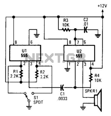
Pulsed sound is produced by this circuit. U1 is used as a bistable multivibrator, which acts as a contact debouncer for S1. C1 feeds a trigger pulse to U2, which then generates a pulse to SPKR1, a piezo transducer....
The following circuit illustrates the IC BA1404 used in a stereo FM transmitter circuit diagram. Features include ease of construction, making it accessible for anyone to build. The BA1404 is a versatile integrated circuit designed specifically for FM transmission applications....
This is an AM transmitter schematic diagram. The circuit is divided into two halves: an audio amplifier and an RF oscillator. The oscillator is constructed around Q1 and its associated components. The tank circuit, consisting of L1 and VC1,...
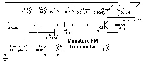
Construct a simple mini FM transmitter. This engaging project demonstrates how to create a mini broadcasting transmitter capable of transmitting an audio signal up to a quarter mile to any FM receiver. It is straightforward to assemble and offers...
The transmitting signal can be picked up by any FM radio receiver. Most often used in cars. The problem with most FM transmitters is that they have very weak signals and short transmitting ranges. Some units are so poor...
This infrared transmitter utilizes pulse width modulation (PWM). The transmitter is equipped with an LM567 tone decoder circuit. An audio signal (at least 50 mV peak-to-peak) is amplified with transistor T1 and subsequently used to modulate IC1. The frequency...