
VHF field strength meter

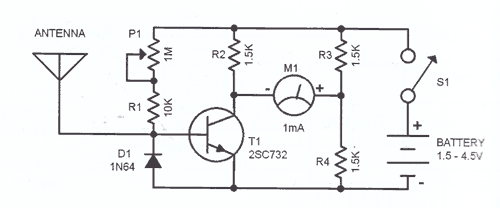
The VHF field strength meter operates on the principle of converting radio frequency (RF) signals into a measurable direct current (DC) voltage. The core components of the circuit include a coil for RF signal reception, a diode (D1) for rectification, a field-effect transistor (FET) for amplification, and a meter (M1) for displaying the signal strength.
When an RF signal is received by the coil, it generates an alternating current (AC) voltage that is rectified by diode D1, converting it into a DC voltage. This DC voltage is crucial as even a minimal change can influence the biasing of the FET. The FET acts as a sensitive amplifier, ensuring that even weak signals can be detected and indicated on the meter.
Calibration of the meter is achieved using a preset resistor (R2). By adjusting this resistor, the user can set the meter (M1) to read zero when no RF signal is present, ensuring accurate measurements when signals are detected.
The sensitivity of the circuit is moderate; it is designed to detect signals from handheld FM transmitters within a range of a few meters. This makes it suitable for educational purposes and theoretical demonstrations, where the emphasis is on understanding the principles of RF signal detection rather than high sensitivity or precision.
Overall, this simple VHF field strength meter serves as an effective tool for demonstrating the basic concepts of radio frequency measurement and signal detection in a cost-effective manner.This is a simple and low cost wide band VHF field strength meter. The field strength is measured by converting the radio signal to DC and measuring it. The RF signal will be picked up by the coil and rectified by the diode D1. Even a very small DC voltage is sufficient to alter the biasing of FET and it will be reflected in the meter as an indicati on of the presence of a radio signal. The meter can be calibrated by adjusting the preset R2 to make meter M1 read ZERO in the absence of any radio signal. This circuit is not very sensitive, but can sense radio signals from hand held FM transmitters up to a distance of few meters( ideal for theoretical demonstrations).
🔗 External reference
Related Circuits
SWR, or standing wave ratio, is the ratio of the amplitude of a partial standing wave at an antinode (maximum) to the amplitude at an adjacent node (minimum). SWR is a critical parameter in RF (radio frequency) engineering, particularly in...
This is it. It's a STEREO LED LEVEL METER. It's the cheapest and best bar graph display available and best of all, it uses readily available components. You only need a handful of LEDs, 22 transistors, some resistors, diodes,...
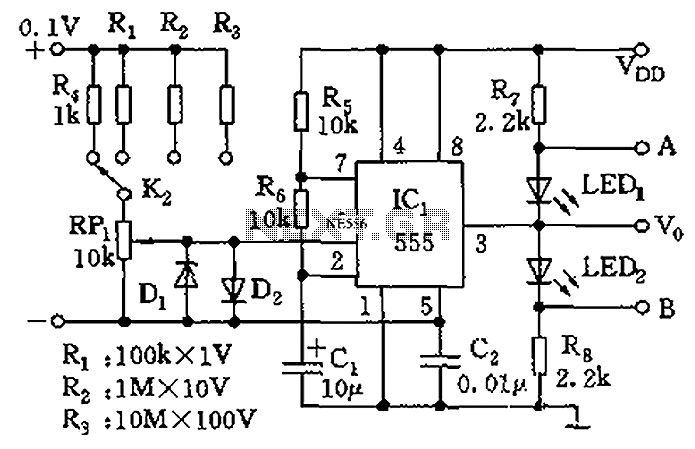
The control terminal at 5 feet and the threshold end at 6 feet represent two internal input voltage comparators. As long as the voltage at 6 feet exceeds the voltage at 5 feet by 5 mV, the 555 timer...
Unlike a standard voltmeter, the input of an oscilloscope typically has one side (GND) connected to ground through the mains lead. This connection can lead to significant issues when the measuring probe is attached to a circuit that is...
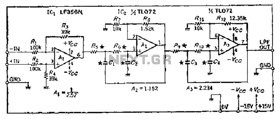
A 24 dB/octave Butterworth filter with a maximally flat characteristic is constructed using two filters, each capable of providing a 12 dB/octave response. This configuration allows for a 3 dB point adjustment. To achieve the desired cutoff frequency, adjustments...
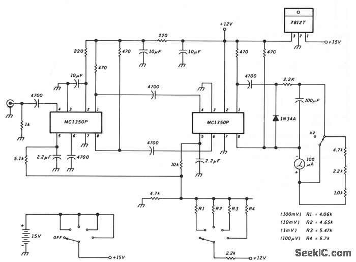
This schematic illustrates a peak-reading diode voltmeter that is powered by two amplification stages. A 100 µF capacitor is utilized to create a substantial time constant, which ensures effective damping of the meter. The restricted differential output voltage, combined...