
Vlf converter
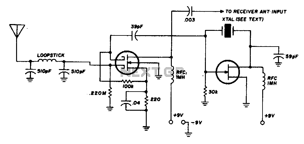
This converter circuit design is characterized by the integration of a low-pass filter, which simplifies the tuning process by eliminating the need for a tuned circuit. The primary focus of tuning is shifted to the receiver, allowing for a more straightforward setup. The use of dual-gate MOSFETs and FETs in the mixer and oscillator stages provides flexibility in component selection, as these elements are not critical to the circuit's performance.
The oscillator's operation is determined by the crystal frequency, which must be compatible with the receiver's tuning range. The example provided illustrates the relationship between the crystal frequency and the receiver dial readings. When a 3500 kHz crystal is used, the receiver is set to 3500 kHz, which corresponds to a zero kHz output. As the receiver dial is adjusted, the frequency readings change linearly; for instance, tuning to 3600 kHz yields an output of 100 kHz, and tuning to 3700 kHz results in an output of 200 kHz.
Furthermore, it is noteworthy that at the setting of 3500 kHz, the primary signal detected is that of the converter’s oscillator. As the frequency is increased, particularly around 20 kHz above the initial setting, very low frequency (VLF) signals begin to emerge. This behavior is crucial for users who may be interested in receiving VLF signals, as it indicates the operational range of the converter in relation to the receiver's tuning capabilities. Overall, the circuit design provides a robust solution for frequency conversion while maintaining ease of use and flexibility in component selection.This converter uses a low-pass filter instead of the usual tuned circuit so the only tuning required is with the receiver. The dual-gate MOSFET and FET used in the mixer and oscillator aren"t critical. Any crystal having a frequency compatible with the receiver tuning range may be used. For example, with a 3500 kHz crystal, 3500 kHz on the receiver dial corresponds to zero kHz; 3600 to 100 kHz; 3700 to 200 kHz, etc
(At 3500 khz on the receiver all one can hear is the converter oscillator, and VLF signals start to come in about 20 kHz higher). 🔗 External reference
Related Circuits
The voltage to frequency converter (V/FC - VCO) circuit consists of a UJT (uni-junction transistor) oscillator in which the timing charge capacitor C2 is utilized. The voltage to frequency converter circuit operates by converting an input voltage into an output...

The 24V to 12V converter schematic is straightforward; however, it is important to ensure that all components, including transistors and integrated circuits, are adequately heat dissipated and electrically insulated from metal surfaces. The schematic diagram is derived from the...
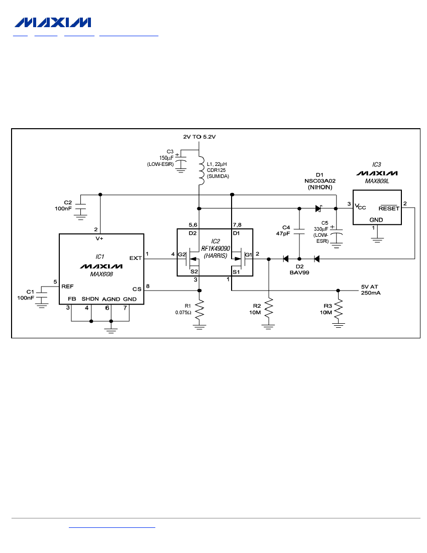
To ensure a full-load start-up, the additional circuitry in this regulated boost converter disconnects the load until the output voltage reaches regulation. Proper operation necessitates a gate-drive voltage adequate to maintain low on-resistance in the switching MOSFET; however, during...
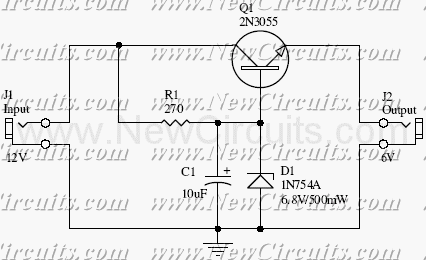
This small but useful circuit is a DC voltage converter for using 6V devices with car battery voltage. The maximum output current is dependent if the T1 is covered with a proper heat sink or not. You can use...
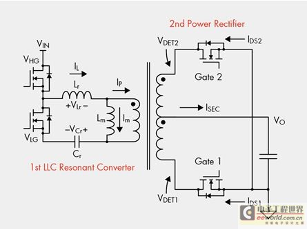
The designer is looking for a solution with higher efficiency and lower power consumption in order to minimize unnecessary energy loss. The approach involves using syntony inductance to harmonize the capacitive LLC syntony converter, employing zero voltage switching (ZVS)...
Most ATV (Amateur Television) transmitters use a DSB (Double Sideband) signal, while commercial television stations utilize a VSB (Vestigial Sideband) signal. This converter takes advantage of the lower sideband, leading to reduced interference from repeaters operating in the 440...
Warning: include(partials/cookie-banner.php): Failed to open stream: Permission denied in /var/www/html/nextgr/view-circuit.php on line 713
Warning: include(): Failed opening 'partials/cookie-banner.php' for inclusion (include_path='.:/usr/share/php') in /var/www/html/nextgr/view-circuit.php on line 713