
Water Activated Relay

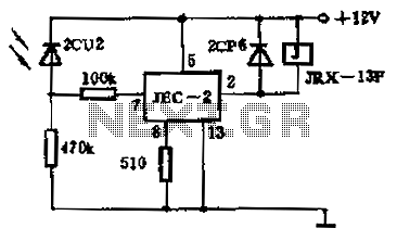
The circuit described utilizes a high-gain compound pair configuration consisting of two bipolar junction transistors (BJTs), specifically the 2N2222A and BC108. The 2N2222A serves as the first transistor (T1), while the BC108 functions as the second transistor (T2). This arrangement is designed to amplify weak signals, with the overall current gain being the product of the current gains (beta) of the two transistors, which are specified to be at least 140 for T1 and 110 for T2. This results in a theoretical maximum current gain of 15,400, providing a significant amplification factor that is advantageous for various applications.
The circuit operates within a power supply voltage range of 4.5 to 15 volts, making it versatile for different electronic applications. The relay used in the circuit is a typical 5-volt relay, which requires a current of 60 mA to activate. The relay's activation is contingent upon detecting a minimum current of 4 microamperes (uA) flowing through the sensing medium, which can be achieved using conductive fluids such as tap water or rainwater. This feature allows the circuit to function effectively as a fluid sensor, where the presence of water completes the circuit and energizes the relay.
In practical implementation, the transistors should be appropriately biased to ensure they operate within their active regions. Proper heat dissipation measures should also be considered, especially for the 2N2222A, as it may generate heat under load conditions. The circuit can be further enhanced with additional components such as resistors for biasing, capacitors for stability, and diodes for flyback protection in relay applications. Overall, this configuration provides a robust solution for fluid detection and control applications, leveraging the high gain characteristics of the transistor pair.In his circuit Marin has used two transistors wired as a high gain compound pair. Transistor T1 may be a 2N2222A and T2 a BC108. The current gain will be the product of each transistors beta, which will be a minimum of 140 x 110 or 15400. The power supply used can be any voltage from 4.5 to 15 volts, a typical 5 volt relay may require 60 mA to operate, in which case any fluid which passes a minimum current of 4 uA will activate the relay.
This is easily achieved with tap or rain water. 🔗 External reference
Related Circuits
The schematic represents a water level alarm circuit. This circuit functions as a water level sensor and emits a melodious alarm sound when the two probes within the circuit detect the presence of water. This water level indicator circuit...
This is a driving relay circuit utilizing a 555 integrated circuit (IC). The circuit is designed to control a relay and prevent the 555 IC from becoming unresponsive by employing inductive feedback. The coil is safeguarded. The driving relay circuit...
The circuit operates as a photoelectric switch utilizing a photoresistor. It exhibits high sensitivity, particularly in controlling a light relay. Under low illumination, the transistor (VT) remains non-conductive. When the illumination reaches a certain threshold, the resistance of the...
The schematic presented is a circuit designed for monitoring plant watering, also known as a dry soil detector. Indoor plants, whether in homes or offices, require more attention compared to outdoor plants. Due to busy schedules, it is common...
The circuit operates based on a desired temperature setting. It can be utilized for various applications, such as turning on a fan at a specified temperature or activating an emergency temperature alarm. The power supply for the circuit can...
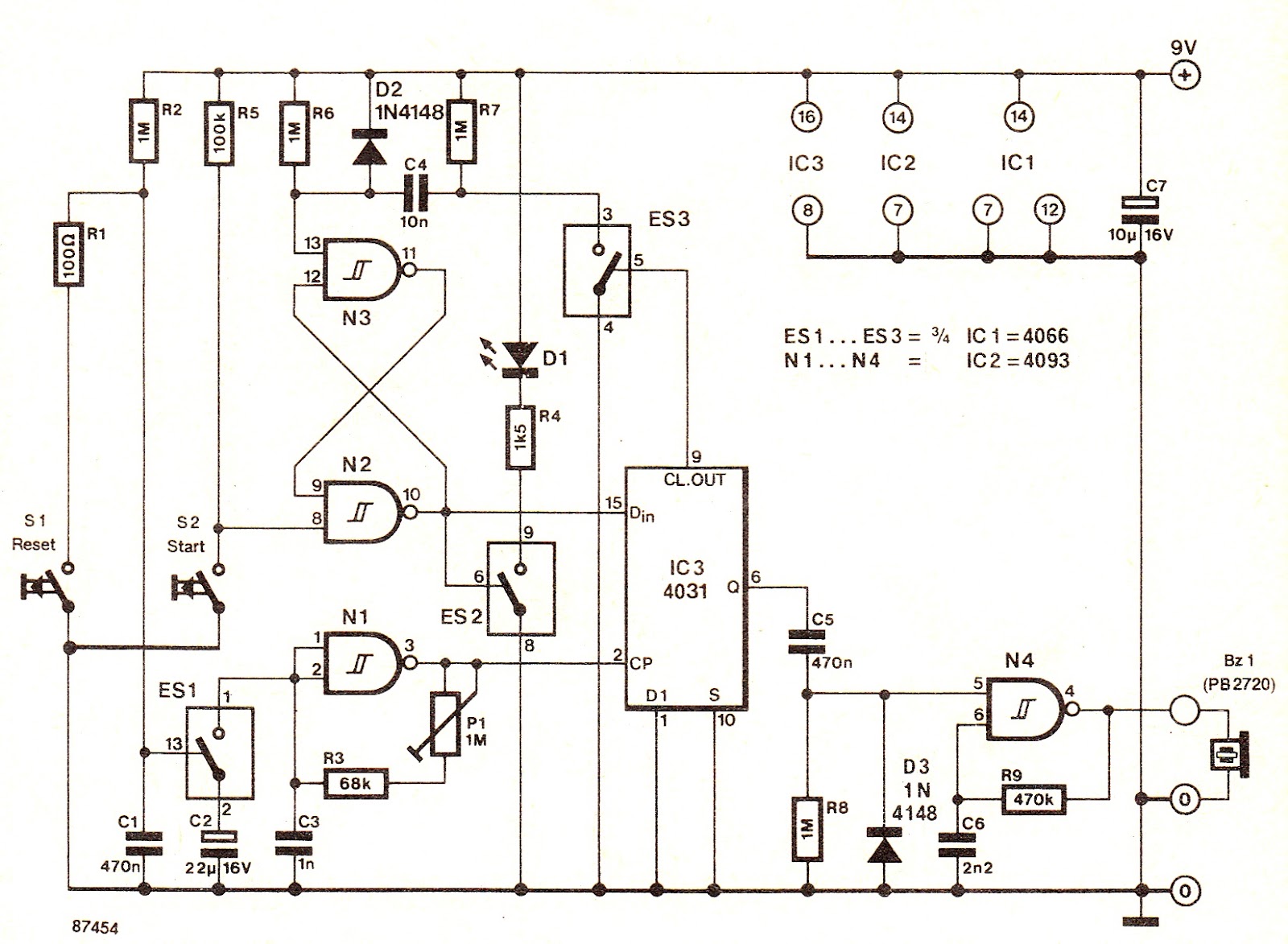
The electronic switch ES1 connects the frequency-determining capacitor to the input of clock oscillator N1. The logic level present at the Dm terminal of the integrated circuit is shifted to output Q at a speed defined by P1, allowing...