
dvi to par digital video interface with lcd

The dvi2par also includes optional I2C EEPROM support, allowing it to be used with hosts other than the BeagleBoard, which supports the display's DDC/EDID configuration. However, this feature has only been verified to work on a standard Linux desktop PC. Since it is not necessary on the BeagleBoard, it has not been tested in detail. To use this feature, an EDID description for the specific display must be created using the Phoenix EDID Designer 1.3 (a Windows software that operates well in Wine). The output from this editor must then be programmed into the dvi2par DDC EEPROM. The jumper JP1 must be set to enable writing to the EEPROM. The I2C port of the HDMI connector should be connected to Linux-controlled I2C hardware, such as an I2C-tiny-USB.
The following components were sourced from Germany from Reichelt and Conrad:
- Part: HDMI connector, Quantity: 1, Reichelt Part No.: 530335-62
- Part: 3.3V regulator, Quantity: 1, Name: LM2937 ET3, Reichelt Part No.: 3
- Part: DDC EEPROM, Quantity: 1, Name: ST 24C01 MN
- Part: TFP101A, Quantity: 1
- Part: Capacitor (10uF/16V SMD), Quantity: 2, Name: TAN. 10/16
- Part: Capacitor (100nF), Quantity: 5, Name: X7R-G0805 100N
- Part: Resistor array (4*22R SMD), Quantity: 7, Name: BCN16 22
- Part: Resistor (4.7k SMD 0805), Quantity: 2, Name: 4.70K
- Part: Resistor (100R SMD 0805), Quantity: 1
- Part: Resistor (47k SMD 0805), Quantity: 2, Name: 47.0K
- Part: Diode (1N 4001 SMD), Quantity: 1, Name: 1N 4001 SV1-SV4, JP1-JP2
- Part: Pin header (1x36), Quantity: 1, Name: SL 1X36G 2.54
- Part: Power connector, Quantity: 1, Name: AKL 101-03
The circuit design involves integrating the TFP101A with the necessary components to ensure compatibility between the 1.8V signals and the 3.3V signals required by LCDs. The circuit must be carefully laid out to accommodate the routing of the SCDT signal to the backlight inverter, ensuring proper operation only when a valid HDMI signal is detected. The optional I2C EEPROM adds flexibility for different display configurations, enhancing the circuit's versatility across various platforms. Proper attention to the layout and connections, particularly regarding the I2C interface and EEPROM programming, is crucial for successful implementation.Unfortunatately this only provides 1. 8v signals and still needs a converter to interface to the 3. 3v signals most raw LCD use. The main components is the TFP101A. I got mine as a free sample from TI. Also visible in this picture is the fact that only the upper 6 of the 8 color bits available on the dvi2par are being used. It`s important to make sure that the upper bits are being used if the display supports less than 24 bit
color depth. Also visible in the image is the fact that a tiny wire goes from pin 8 of the TFP101A to some other parts on the board is mounted on. Pin 8 carries the SCDT signal which indicates that a valid signal has been detected in the input. In this example the signal is routed to the backlight inverter and makes sure that the backlight is only switched on if a valid HDMI signal is being received.
EDID/DDC support The dvi2par also includes an optional i2c eeprom which is meant to allow to use the dvi2par on hosts other than the beagleboard which support to use a displays ddc/edid configuration. However, this part has only been verified to be operational and to be usable on a standard linux desktop PC.
But since this part is not necessary on a beagleboard, it isn`t tested to all detail. In order to use it, you need to build an EDID description for your particular display using e. g. the Phoenix EDID designer 1. 3 (A windows software which runs fine in wine). The output of this editor needs then to be programmed into the dvi2par ddc eeprom. The jumper JP1 has to be set to enable writing the eeprom. The i2c port of the hdmi connector then needs to be connected to some linux controlled i2c hardware like e. g. my i2c-tiny-usb. Below is an image of my i2c-tiny-usb based adptor used to write the ddc eeprom on the dvi2par. All remaining parts have been bought in germany from Reichelt and Conrad. The part numbers are: Part Qty Name Reichelt Part No. Conrad Part No. X1 1 HDMI connector 530335-62 IC1 1 3. 3V regulator LM2937 ET3, 3 IC2 1 DDC eeprom ST 24C01 MN IC7 1 TFP101A C2, C3 2 Capacitor 10uF/16V SMD TAN.
10/16 C1, C4-C7 5 Capacitor 100nF X7R-G0805 100N RN1-RN7 7 Resistor array 4*22R SMD BCN16 22 R1, R3 2 Resistor 4k7 SMD 0805 4, 70K R2 1 Resistor 100R SMD 0805 100 R4, R5 2 Resistor 47k SMD 0805 47, 0K D1 1 Diode 1N 4001 SMD 1N 4001 SV1-SV4, JP1-JP2 1 Pinheader 1x36 SL 1X36G 2, 54 X2 1 Power connector AKL 101-03 🔗 External reference
Related Circuits
The digital readout of the Corsair 560 is positioned above the tuning knob. In this radio, the six-digit display often fluctuated, frequently doubling the frequency indication. The reading was unstable, making it challenging to determine the tuned frequency. After...
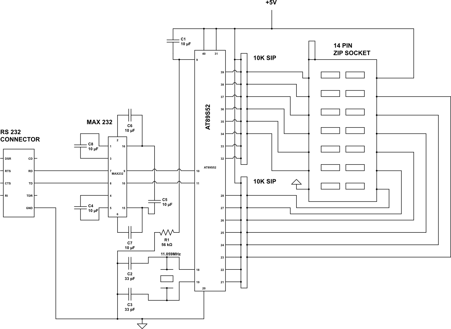
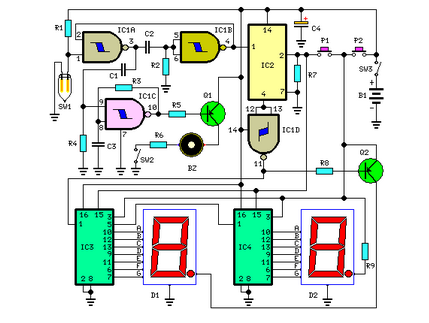
Check the following ICs: 7400, 7402, 7404, 7408, 7432, 7486. A Visual Basic program is utilized to display the results on the PC. The microcontroller AT89S52 receives the IC number from the PC, verifies the logic gates with the...
This circuit provides a visual 9-second delay using a 7-segment digital readout LED. When the switch is closed, the CD4010 up/down counter is preset to 9, and the 555 timer is disabled, holding the output high. When the switch...
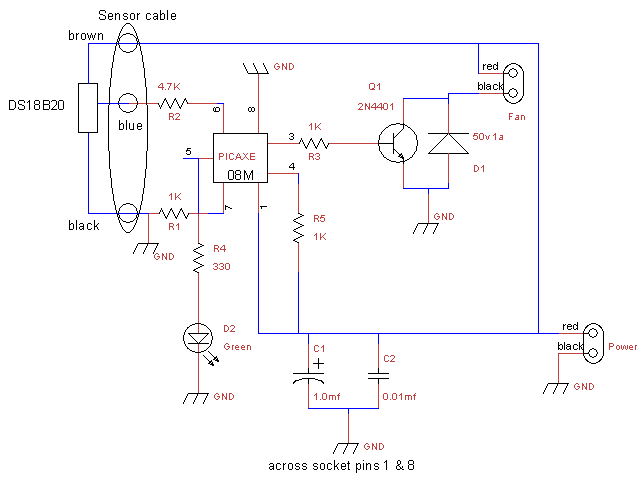
This is a fan controller designed for an audio/video cabinet. It utilizes a PICAXE 08M microcontroller and a DS18B20 temperature sensor. The fan activates at 30 degrees Celsius (approximately 86 degrees Fahrenheit) and deactivates at 28 degrees Celsius (around...
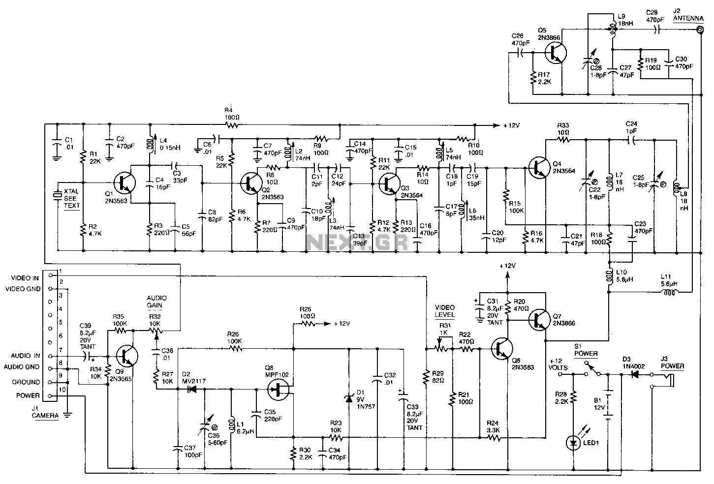
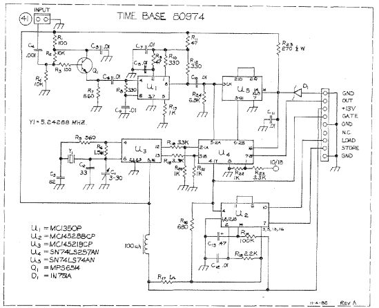
This high-performance video camera link transmits signals from a video camera to a VCR or from a VCR to televisions throughout a home. The initial stage of the RF chain is a crystal-controlled oscillator, Q1, operating at a frequency...
This circuit measures the distance covered during a walk. The hardware is housed in a small box that can be placed in a pocket, and the display is designed as follows: the leftmost display D2 (the most significant digit)...
Warning: include(partials/cookie-banner.php): Failed to open stream: Permission denied in /var/www/html/nextgr/view-circuit.php on line 713
Warning: include(): Failed opening 'partials/cookie-banner.php' for inclusion (include_path='.:/usr/share/php') in /var/www/html/nextgr/view-circuit.php on line 713