
Potentiometric voltmeter
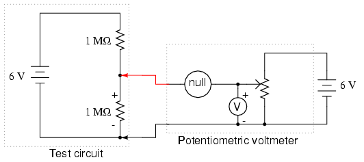
Construct the two-resistor voltage divider circuit as shown in the schematic diagram and illustration. If the two high-value resistors are of equal value, the battery's voltage should be divided in half, with approximately 3 volts dropped across each resistor. Measure the battery voltage directly with a voltmeter, then measure the voltage drop across each resistor. An unusual observation may be noted in the voltmeter's readings. Normally, series voltage drops should equal the total applied voltage, but a significant discrepancy may be observed. This is not a violation of Kirchhoff's Voltage Law. The explanation is that connecting a voltmeter across either resistor alters the circuit, resulting in a voltage reading that differs from the scenario without the meter connected. An analogy can be drawn to an air pressure gauge used to check a pneumatic tire's pressure; when the gauge is connected, it releases some air, affecting the pressure reading. In a similar manner, voltmeters influence the voltage they measure by bypassing some current around the component whose voltage drop is being measured. Although this effect is typically negligible, it becomes pronounced in this circuit.
To further investigate, replace the two high-value resistors with two 100 kΩ resistors and repeat the experiment. Then, replace those resistors with two 10 kΩ units and observe any changes in the voltage readings. This will provide insight into the voltmeter's impact on a circuit concerning the circuit's resistance. Ensure that any low-value resistors are replaced with the original high-value (≥ 1 MΩ) resistors before proceeding. Measure the voltage across the two high-value resistors one at a time using a digital voltmeter instead of an analog voltmeter. Notable differences may be observed between the readings of the digital and analog meters. Digital voltmeters typically exhibit higher internal (probe-to-probe) resistance, resulting in lower current draw compared to an analog voltmeter when measuring the same voltage source. An ideal voltmeter would draw no current from the circuit under test, thereby avoiding voltage impact issues. If two voltmeters are available, connect one across one resistor and the other across the second resistor. In this case, the voltage readings should add up to the total voltage, indicating a more accurate measurement.The potentiometer value is not critical: anything from 1 k © to 100 k © is acceptable. If you have built the "precision potentiometer" described earlier in this chapter, it is recommended that you use it in this experiment. Likewise, the actual values of the resistors are not critical. In this particular experiment, the greater the value, the bett er the results. They need not be precisely equal value, either. If you have not yet built the sensitive voltage detector, it is recommended that you build one before proceeding with this experiment! It is a very useful, yet simple, piece of test equipment that you should not be without. You can use a digital multimeter set to the "DC millivolt" (DC mV) range in lieu of a voltage detector, but the headphone-based voltage detector is more appropriate because it demonstrates how you can make precise voltage measurements without using expensive or advanced meter equipment.
I recommend using your home-made multimeter for the same reason, although any voltmeter will suffice for this experiment. Build the two-resistor voltage divider circuit shown on the left of the schematic diagram and of the illustration.
If the two high-value resistors are of equal value, the battery`s voltage should be split in half, with approximately 3 volts dropped across each resistor. Measure the battery voltage directly with a voltmeter, then measure each resistor`s voltage drop. Do you notice anything unusual about the voltmeter`s readings Normally, series voltage drops add to equal the total applied voltage, but in this case you will notice a serious discrepancy.
Is Kirchhoff`s Voltage Law untrue Is this an exception to one of the most fundamental laws of electric circuits No! What is happening is this: when you connect a voltmeter across either resistor, the voltmeter itself alters the circuit so that the voltage is not the same as with no meter connected.
I like to use the analogy of an air pressure gauge used to check the pressure of a pneumatic tire. When a gauge is connected to the tire`s fill valve, it releases some air out of the tire. This affects the pressure in the tire, and so the gauge reads a slightly lower pressure than what was in the tire before the gauge was connected. In other words, the act of measuring tire pressure alters the tire`s pressure. Hopefully, though, there is so little air released from the tire during the act of measurement that the reduction in pressure is negligible.
Voltmeters similarly impact the voltage they measure, by bypassing some current around the component whose voltage drop is being measured. This affects the voltage drop, but the effect is so slight that you usually don`t notice it. In this circuit, though, the effect is very pronounced. Why is this Try replacing the two high-value resistors with two of 100 k © value each and repeat the experiment.
Replace those resistors with two 10 K © units and repeat. What do you notice about the voltage readings with lower-value resistors What does this tell you about voltmeter "impact" on a circuit in relation to that circuit`s resistance Replace any low-value resistors with the original, high-value (>= 1 M ©) resistors before proceeding. Try measuring voltage across the two high-value resistors - one at a time - with a digital voltmeter instead of an analog voltmeter.
What do you notice about the digital meter`s readings versus the analog meter`s Digital voltmeters typically have greater internal (probe-to-probe) resistance, meaning they draw less current than a comparable analog voltmeter when measuring the same voltage source. An ideal voltmeter would draw zero current from the circuit under test, and thus suffer no voltage "impact" problems.
If you happen to have two voltmeters, try this: connect one voltmeter across one resistor, and the other voltmeter across the other resistor. The voltage readings you get will add up to the total voltage this time, no matt 🔗 External reference
Related Circuits
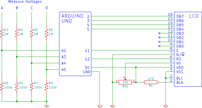
An Arduino voltmeter that displays voltage on an LCD display. The voltmeter has 4 channels for measuring four different voltages. The Arduino voltmeter utilizes an Arduino microcontroller to measure and display voltage levels on a Liquid Crystal Display (LCD). This...
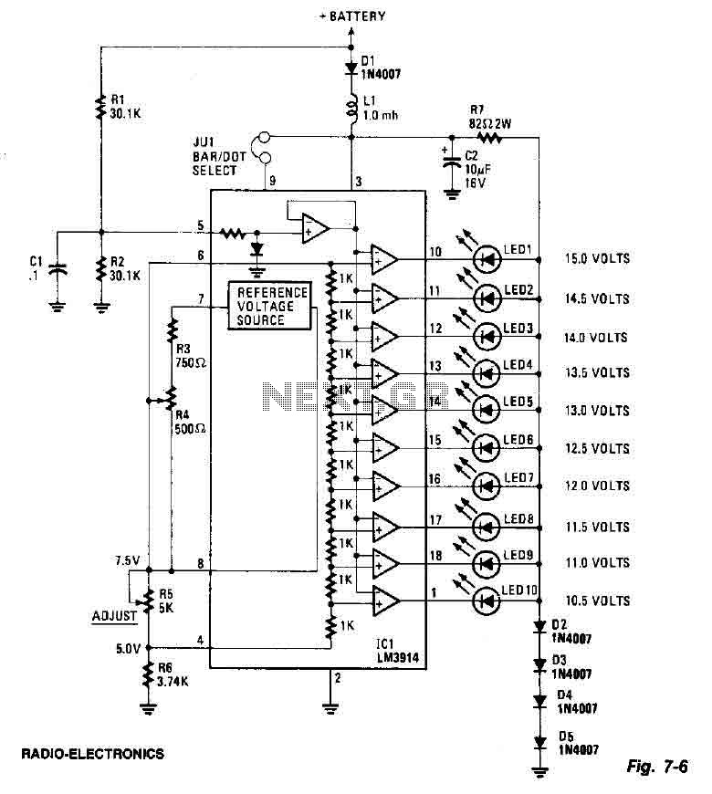
This screen utilizes ten LEDs to indicate a voltage range from 10.5 to 15 volts, with each LED corresponding to a 0.5-volt increment. The core component of the circuit is the LM3914 LED bar graph/display driver. A trimming potentiometer,...
The circuit is a comparator that can measure the voltage of a car battery in steps of 1 Volt. The voltage is determined after comparing the voltage of the battery, which is applied to the inverting inputs of amplifiers,...
Below is a comparator circuit that can measure the voltage of a car battery in 1-volt steps. The voltage indication is achieved through a comparison mechanism. The described comparator circuit is designed to accurately measure and indicate the voltage level...

This circuit is designed to provide an affordable method for creating a high impedance voltmeter using a low-cost analog or digital multimeter. The circuit is specifically intended for testing phototransistors. When measuring voltages in high resistance circuits, the resistance...

This document explains how to construct a voltmeter for measuring DC voltage without utilizing a multimeter. It describes a straightforward digital voltmeter circuit capable of measuring voltages ranging from 0V to 9V. The primary component of this circuit is...