
Arduino How to control a Servo
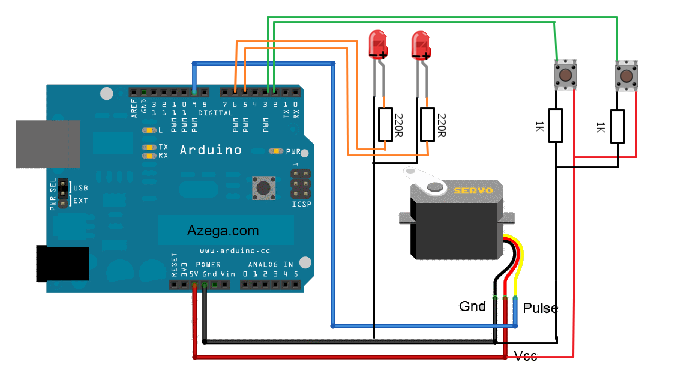
In this circuit design, the primary components include an Arduino microcontroller, a servo motor, two momentary push buttons, an LED indicator, and an IR sensor. The Arduino serves as the control unit, executing the logic for button presses and managing the servo's position.
The circuit configuration involves connecting the two push buttons to digital input pins on the Arduino. When a button is pressed, it sends a signal to the Arduino, which then determines the direction of the servo's rotation. The left button is connected to one digital pin, while the right button is connected to another. Each button should also have a pull-down resistor to ensure a stable low signal when the button is not pressed.
The servo motor is connected to a PWM-capable pin on the Arduino. The Arduino's servo library allows for easy control of the motor's angle, typically ranging from 0 to 180 degrees. The corresponding LED indicators are connected to separate digital output pins, and their state is controlled by the Arduino based on the button pressed.
The IR sensor, which is also connected to the Arduino, can be powered through one of the Arduino's output pins. This sensor will be mounted on the servo, allowing it to sweep continuously as the servo rotates. The data from the IR sensor can be processed to detect obstacles or measure distance, depending on the application.
This circuit design not only demonstrates basic control of a servo motor but also integrates sensor functionality, showcasing the versatility of Arduino in handling multiple input and output devices simultaneously. The use of LED indicators provides visual feedback, enhancing the user experience by clearly showing the direction of the servo's movement. Careful attention should be paid to the power requirements of the servo and the IR sensor to ensure stable operation within the circuit.In this one, servo is programmed to be controlled by two buttons, one turns servo to the left and the other one turns it to the right. When the servo is turning, corresponding LED will be switched on to indicate the operation. Because Arduino has built-in library for controlling servo, which makes servo a really easy kit to use.
In this project, I will be using a servo to turn the IR sensor around constantly. 🔗 External reference
Related Circuits
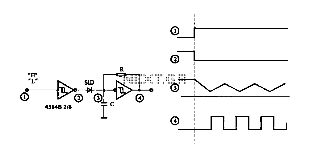
The circuit generates a controlled pulse signal. When a high pulse signal is applied to the input terminal O (start), the output pulse signal is activated. Conversely, when a low signal is received at the input terminal O (stop),...
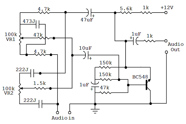
An audio equalizer circuit is utilized to modify the frequency response of an audio signal. This particular equalizer circuit is designed for adjusting the bass and treble (tone) levels of an audio amplifier. To integrate this equalizer circuit with...
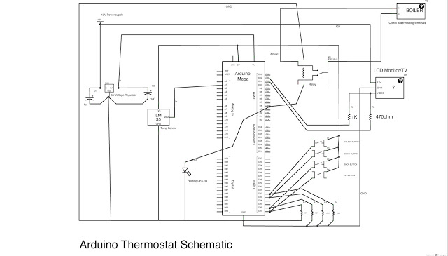
This post outlines the steps taken to build an Arduino-based thermostat, as demonstrated in accompanying videos. The first video showcases a preliminary version of the menu system, providing an overview of the features. The second video presents the completed...
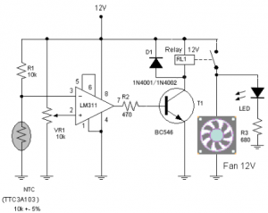
The circuit schematic diagram of a fan speed control system that activates only when necessary. When the transistor heats up, the fan will automatically turn on. The fan speed control circuit operates based on the temperature of the transistor, utilizing...
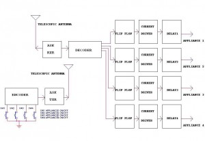
This circuit illustrates a remote control circuit diagram using RF technology without the use of a microcontroller. Features include a simple remote control circuit that operates via radio frequency. The remote control circuit operates by transmitting signals through radio waves,...
Upon purchasing the slave dial, it arrived without instructions, packaging, or additional details. The only visible markings, aside from decades of grime, were on the face (SMITH SECTRIC, ACELEC SYDNEY) and some markings on the bracket holding the mechanism...