
Audio Memo Alert Circuit

The device operates on a simple yet effective principle utilizing a conductive switch mechanism. When a paper note is inserted between two conductive fingers, the electrical circuit is interrupted, triggering a change in voltage that is detected by operational amplifier Ul-a. This amplifier is configured as a comparator, where the input from the conductive fingers determines the output state. When the circuit is broken, the output of Ul-a transitions to a high state, indicating that a note is present.
The high output from Ul-a is then fed into a pair of additional operational amplifiers, Ul-c and Ul-d, which are configured to function as an oscillator. This oscillator generates a square wave signal at a specific frequency, which is then used to drive the piezo buzzer BZ1. The pulsing of the buzzer serves as an alert mechanism, ensuring that the presence of the note is not overlooked.
The circuit design may include additional components such as resistors and capacitors to stabilize the oscillation frequency and manage the power supplied to the buzzer. The choice of conductive materials for the fingers is crucial, as it must ensure reliable circuit interruption while being sensitive enough to detect the presence of a paper note.
Overall, this device combines simple electronic components to create an effective reminder system, enhancing the visibility of important notes and memos through auditory signals. The schematic would typically include the operational amplifiers, the buzzer, and the necessary passive components to complete the circuit functionality. This device prevents paper notes and memos from being overlooked. A paper note placed between two fingers made of a conducting material (metal or conductive plastic) breaks the circuit, allowing pair 1 of Ul-a to go high. This causes Ul-c Ul-d to act as an oscillator, pulsing piezo buzzer BZ1. 🔗 External reference
Related Circuits

A basic LED driver circuit consists of a 5-volt power source, a 2 kΩ potentiometer, and an LED. The LED is forward biased, with the manufacturer specifying a maximum current rating of 20 mA at a diode voltage drop...
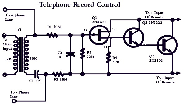
This circuit will allow you to connect any tape recorder that has a mic and remote input to a phone line and automatically record both sides of a conversation whenever the phone is in use. You will need to...

This sensor switch circuit features nine channels and consists of three integrated circuits along with several resistors. The 74HC147, which has a high input impedance, enables the use of 4.7 MΩ resistors to establish a logic level "high" for...

This page outlines the development of electronics for displaying a monochrome video image on an electrostatic oscilloscope tube. This work complements the Electron Optics section in the Experiments category. The primary objective is to showcase a moving video image...

This circuit diagram represents a lamp flasher powered by mains electricity. It is capable of flashing lamps with a maximum power of 200 Watts at user-defined rates. The NE555 integrated circuit is configured as an astable multivibrator, generating the...

This circuit creates an LED color fade effect. As indicated by the name, the light intensity of the LEDs in this circuit transitions from high intensity to low intensity and eventually turns off. A 30 µF capacitor and a...
Warning: include(partials/cookie-banner.php): Failed to open stream: Permission denied in /var/www/html/nextgr/view-circuit.php on line 713
Warning: include(): Failed opening 'partials/cookie-banner.php' for inclusion (include_path='.:/usr/share/php') in /var/www/html/nextgr/view-circuit.php on line 713