
General use Preamplifier with 2N3904
The universal preamplifier circuit is designed to accommodate various audio sources by adjusting its gain characteristics through a flexible feedback network. The primary function of this circuit is to amplify low-level audio signals from sources such as microphones and turntables, ensuring optimal signal integrity and compatibility with downstream audio processing equipment.
In the circuit configuration, a high-gain linear amplifier is employed, typically utilizing an operational amplifier (op-amp) as the core component. The op-amp is configured in a non-inverting mode, allowing for high input impedance, which is essential for interfacing with sensitive audio sources. The gain of the amplifier is determined by the feedback resistors connected to the op-amp's feedback loop.
The selector switch S1-a allows for the selection of different audio input sources. When the switch is set to the Mag phono position, it engages a specific pathway tailored for magnetic phono cartridges, which require RIAA equalization to compensate for the frequency response of vinyl records. This equalization is achieved through a combination of capacitors and resistors that form a filter network, specifically designed to boost low-frequency signals and attenuate high-frequency signals, aligning the output with standard RIAA playback curves.
The feedback resistors S1-b are critical in adjusting the gain of the preamplifier. By providing a choice of resistor values—220K, 470K, and 1M ohms—the circuit allows the user to customize the gain according to personal preferences and the specific requirements of the audio source. The relationship between the feedback resistor value and the circuit gain is direct; higher resistance values result in increased gain, while lower values provide reduced amplification.
The range of feedback resistor values from 10 kilo ohms to 10 megohms further enhances the versatility of the preamplifier, accommodating a wide array of audio devices and listener preferences. This adaptability is crucial in professional audio applications, where precise control over signal amplification can significantly impact sound quality and overall system performance.
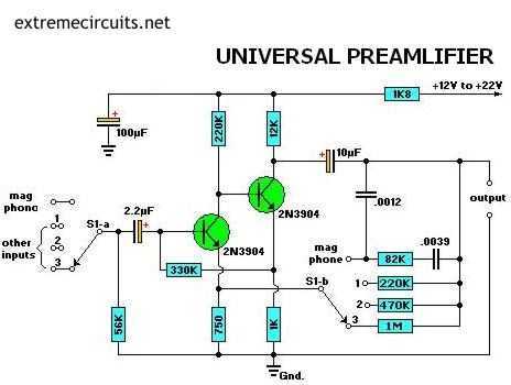
In summary, the universal preamplifier circuit serves as a vital component in audio amplifier systems, providing the necessary gain adjustments and equalization to ensure high-fidelity sound reproduction across various audio sources.Most audio amplifier systems must have preamplifiers with many different characteristics. These include high-gain linear response for magnetic microphones, low-gain linear response for tuners, and high-gain RIAA equalization for magnetic phone cartridges. To meet this broad requirement, most amplifier designers include a single universal preamplifier circuit.
Basically a high-gain linear amplifier, its characteristics can be altered by switching alternative resistor filter networks into its feedback system. For example, when the selector switch is set to the Mag phono position, alternative input sources can be selected by S1-a, and appropriate linear-response gain control feedback resistors 220K, 470K, and 1M are now selected by S1-b. Those feedback resistor values are selected between 10 kilo ohms and 10 megohms to suit individual listener tastes.
Circuit gain will be proportional, to the feedback resistor value. 🔗 External reference
Related Circuits
This is a simple low-impedance preamplifier circuit diagram used to amplify an audio signal. The circuit operates with a 12V DC power source and is straightforward due to its minimal component count. The low-impedance preamplifier circuit is designed to enhance...
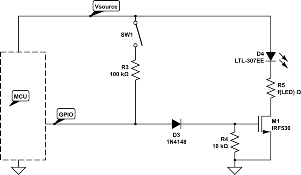
A bicycle light control circuit that reads various buttons and sets multiple outputs such as headlights, taillights, and blinkers. The design utilizes an ATtiny24 microcontroller, operating at an internal oscillator frequency of 8 MHz, and is programmed in C...
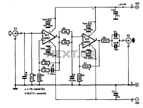
This amplifier is designed to be integrated with preamplifiers that lack a phono input. A phono input is essential for standard record players equipped with dynamic pick-ups, which remain widely used. The amplifier not only elevates the output of...
This application note describes the implementation of a single-supply triangular wave oscillator using the MAX9000 integrated circuit and several passive components. The circuit employs an operational amplifier, a comparator, and a voltage reference as the main active components. The...
This device, available in a Stainless DIL 8 package, is capable of measuring four independent analog voltages ranging from 0 to 5 volts. It transmits the measurement results as four characters via a standard asynchronous serial link. The described device...
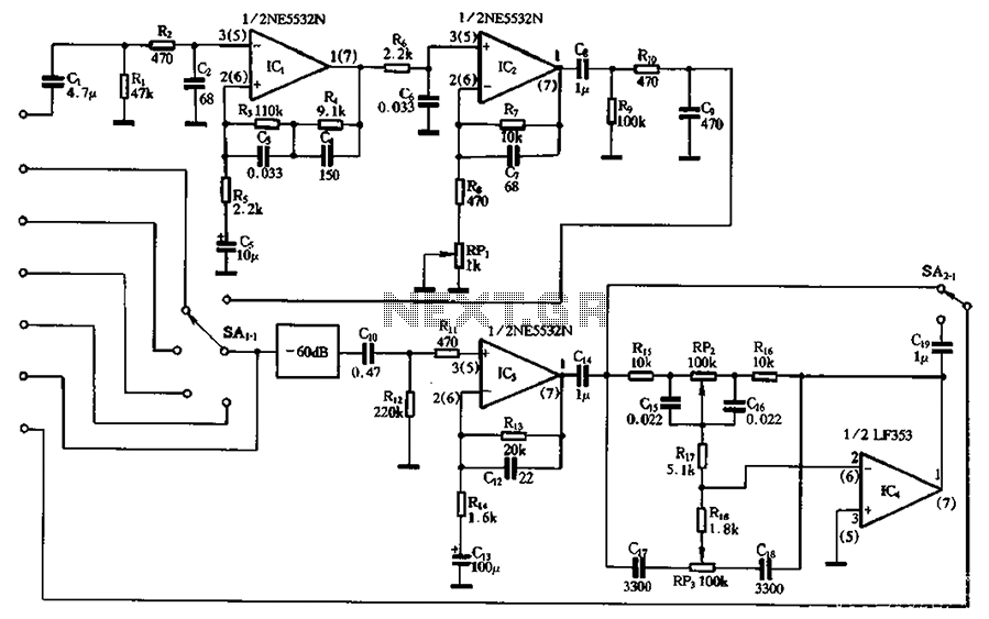
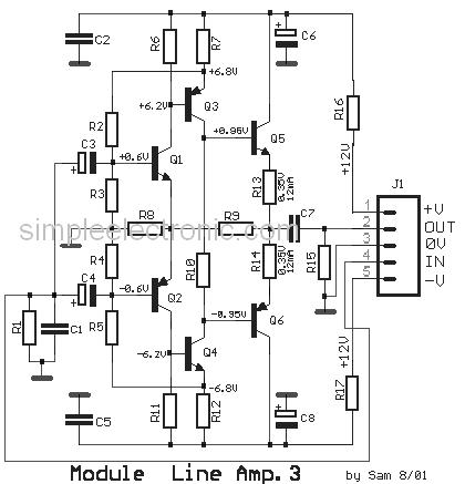
The circuit depicted involves a main amplifier balanced by an electromagnetic pickup, line amplifiers, and a high tone control circuit. It includes components for an electromagnetic player, radio tuner, tape playback, and line input. The preamplifier utilizes an NE5532...