
Automatic Headlight Brightness Switch
The circuit operates by utilizing a light sensor or phototransistor that detects the presence of oncoming headlights. When the sensor detects light above a certain threshold, it triggers a relay or a transistor switch, which then toggles the headlight configuration from high beam to low beam. This automatic adjustment enhances driving safety by preventing glare for oncoming drivers.
The schematic typically includes a power source, which can be the vehicle's battery, connected to the light sensor. The output of the light sensor interfaces with a relay circuit. The relay is designed to handle the current required for the headlight system and is activated by the sensor's output. A diode may be included in the circuit to protect against back EMF generated by the relay coil when it is de-energized.
In addition, a resistor may be used in series with the light sensor to limit current and protect it from excessive voltage. The circuit should also include a capacitor to filter out noise and provide stable operation. The final implementation requires careful consideration of the vehicle's electrical system to ensure compatibility and safety. Proper insulation and mounting of components are essential to prevent short circuits and ensure reliable operation under various environmental conditions.This simple circuit can be wired into your headlight switch to provide automatic switching between high and low beam headlights when there is oncoming traffic. Simple electronics project with circuit diagram.. 🔗 External reference
Related Circuits
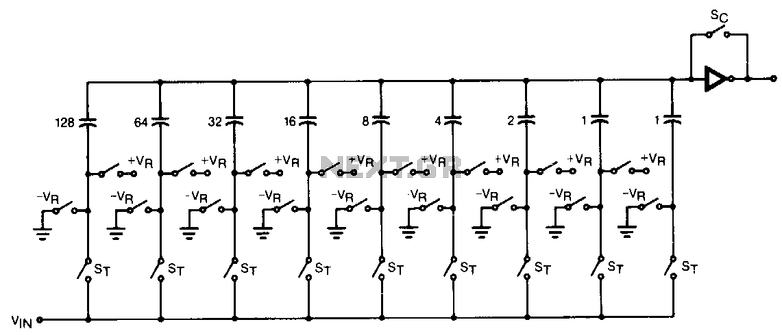
The CMOS comparator in the successive-approximation system determines each bit by examining the charge on a series of binary-weighted capacitors. In the first phase of the conversion process, the analog input is sampled by closing switch SC and all...
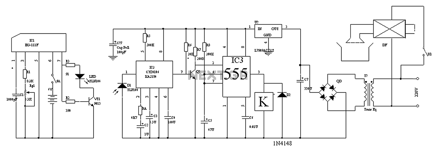
The circuit diagram for the automatic control of drinking fountains is presented below. The automatic control circuit for drinking fountains typically employs a combination of sensors and control elements to manage the operation of the fountain efficiently. The main components...

The phase and neutral wires from the power source have already been connected to electrical appliances such as fans and light points. According to the UPS connection diagram, an additional phase wire should be connected to those appliances where...
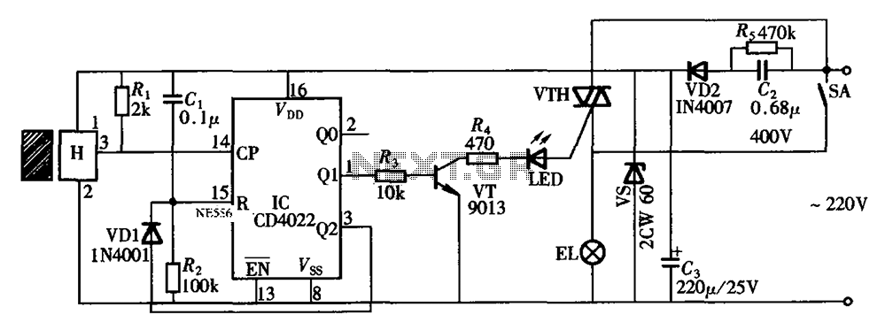
The circuit illustrated in the figure depicts an automatic bathroom light switch system. When the door is opened, the light is activated, illuminating the space. Conversely, when the door is opened again, the light turns off. The circuit comprises...

The circuit consists of two main sections: a charger power supply and an LED driver. The charger power supply is designed using a 3-terminal adjustable regulator (IC1) LM317, while the LED driver is based on a BD140 transistor (T2)....
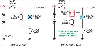
Two headlight reminder circuits are designed for easy installation and operation based on the KISS (Keep It Simple Stupid) principle. The basic circuit consists of a 12V piezo buzzer connected between the lights circuit and a door switch. The...