
Buffering TMP01 Temperature Sensor

The buffer circuit designed for the TMP01 temperature sensor serves to isolate the sensor's output from the load, ensuring that the sensor's performance is not affected by variations in load impedance. The TMP01 sensor provides an analog voltage output that is directly proportional to the ambient temperature, with a sensitivity of 5 mV per Kelvin. This means that for every degree Kelvin change in temperature, the output voltage changes by 5 mV.
In the schematic, the buffer circuit typically employs an operational amplifier (op-amp) configured as a voltage follower. The op-amp's non-inverting input is connected to the output of the TMP01 sensor, while the inverting input is connected to the op-amp output. This configuration allows the op-amp to provide high input impedance and low output impedance, enabling it to accurately follow the sensor's output voltage without loading it down.
Power supply connections for the op-amp must be considered, usually requiring dual supply voltages (e.g., ±15V or a single supply of 0V to 30V) depending on the op-amp specifications. Additionally, bypass capacitors should be placed near the power supply pins of the op-amp to filter out any high-frequency noise that may affect the performance of the circuit.
The output from the buffer can then be fed into an analog-to-digital converter (ADC) or other processing circuits, ensuring that the temperature readings are stable and accurate. Proper layout and grounding techniques should be applied to minimize noise and interference in the circuit, which is critical for maintaining the integrity of the temperature measurements provided by the TMP01 sensor.This is a buffer circuit for TMP01 Temperature Sensor. The output of this sensor is a low impedance dc output voltage with a 5 mV/K temperature coefficient.. 🔗 External reference
Related Circuits
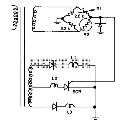
Resistors R1, R2, and the two 2.2 kΩ resistors form a bridge circuit. R2 is a thermistor, and R1 sets the temperature at which L2 lights. Lower or higher temperatures light L1 or L3 to indicate an over- or...

A total of 45 pieces of 220-ohm resistors were used to create a 10k-ohm variable resistor. By bending the wire of the resistor, a hook was formed for sewing purposes. For a more compact design than a standard resistor,...
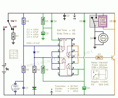
The following circuit illustrates a BC 547 transistor used in a garage alarm sensor circuit diagram. Features include a simple single-zone burglar alarm circuit. The BC 547 transistor is a popular NPN bipolar junction transistor (BJT) that is frequently used...

The CCD camera sensor is a very useful device that is compact in size while providing excellent quality. It can be easily installed with a television through the video input terminals, allowing for the transmission of modulated video signals...
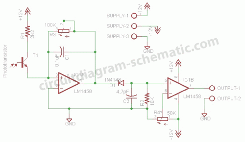
This circuit is a motion detection sensor that utilizes a light source and detector as an infrared motion detector. The motion sensor employs an infrared LED and a phototransistor. Since it relies on light, the sensor's sensitivity can be...
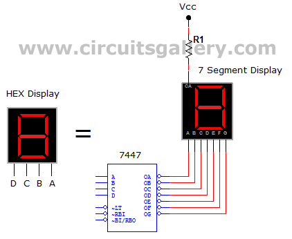
This circuit defines seven levels in a reservoir. The sensed values are connected to an encoder circuit, which consists of a 74148 integrated circuit (IC), functioning as an 8-line to 3-line encoder. The next section features a HEX display,...