
build automatic car battery charger

The Automatic Battery Charger project involves creating a circuit that can efficiently charge batteries without requiring constant supervision. The design typically includes several key components: a power supply, charging circuitry, a control system, and various safety features.
The power supply provides the necessary voltage and current to charge the battery. It may utilize an AC to DC converter if the input is from an AC source. The charging circuitry is responsible for regulating the voltage and current supplied to the battery, ensuring that it is charged according to the specifications of the battery type being used.
A microcontroller or a dedicated charging IC can serve as the control system. This component monitors the battery's voltage and current levels and adjusts the charging parameters accordingly. It can also incorporate features such as temperature sensing to prevent overheating and timers to manage charging cycles.
Safety features are crucial in any battery charging system. These may include over-voltage protection, over-current protection, and short-circuit protection to ensure the safe operation of the charger and the longevity of the battery.
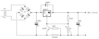
The schematic for this project would typically include connections for the input power, the battery to be charged, and the various components mentioned. Proper layout and component selection are essential for optimal performance and reliability. The circuit can be built on a PCB or a breadboard for prototyping, with careful attention paid to the placement of components to minimize noise and enhance efficiency.
This project not only provides practical experience in electronics but also results in a functional device that can be used to maintain battery health over time.This is a project for those who want to build their very own Automatic Battery Charger. This is a project made by duc_tech.. 🔗 External reference
Related Circuits
The battery charger circuit described is straightforward to assemble, requiring only a few inexpensive components and an additional winding on the power transformer (or a separate transformer). Since this charger operates independently of sound reproduction, there are no stringent...
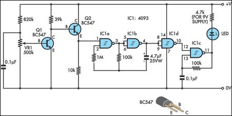
This design integrates power-on and low-battery indication features, capable of operating with any battery voltage up to 15V. It has a very low current drain of 2mA or less and is cost-effective, priced under $3.50 with new components. When...
Many antique radios operate on batteries, including tube portables like the Zenith model K-401 and "farm" radios used in rural areas without electrical power. This article provides historical context on battery usage in early radios and offers guidance on...
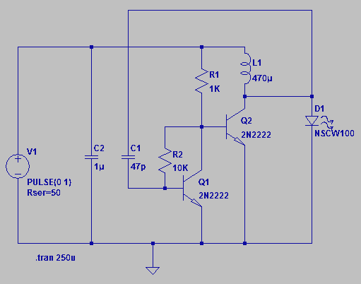
Four observations regarding the Joule Thief AA battery LED circuit. The schematic of the LED circuit illustrates the power source (V1), which symbolizes a depleted battery with only 1 volt remaining and an internal resistance. The Joule Thief circuit is...

This circuit is designed as a low dropout charger using a MOSFET as the pass element; however, it does not incorporate current limiting. The circuit diagram illustrates a straightforward design. It utilizes Q3 and a Schottky diode to isolate...
Figure 1 illustrates a schematic arrangement featuring four batteries. The diagram in Figure 2 employs a voltmeter and a two-pole multi-position rotary switch to select which battery to monitor. Although this design effectively moves the battery metering out of...