
4017 IC For Flip-Flop Timer Circuit DIagram
The 4017 decade counter IC is commonly used in timer and counting applications. In this circuit, the 4017 is configured to operate as a flip-flop timer. The push-button switch (S1) serves as the trigger mechanism for initiating the timing sequence. When pressed, S1 allows capacitor (C1) to discharge through resistor (R2), creating a timing interval based on the RC time constant defined by the values of R2 and C1.
The output of the 4017 IC can be connected to various load devices, such as LEDs or relays, to indicate the timing intervals visually or to control other electronic components. The timing can be adjusted by changing the values of R2 and C1, allowing for flexibility in the duration of the timer.
Additionally, the circuit may include other components such as diodes for protection against reverse polarity, or additional resistors to fine-tune the timing characteristics. The design ensures that the circuit operates reliably and provides a clear indication of the timing cycle through the output states of the 4017 IC.This circuit shows about 4017 IC For Flip-Flop Timer Circuit DIagram. Features: Push-button S1 will discharge capacitor C1 through R2. Component: .. 🔗 External reference
Related Circuits
The finger, positioned within a light screen, is situated between a high-intensity LED emitter and a photocell. It generates a heartbeat signal that, when appropriately amplified, serves as the input for a PIC16F84 microcontroller. The microcontroller drives three common...
This device is a simple timer that keeps the headlights of a vehicle on for approximately 1 minute and 30 seconds, allowing access to dark areas without the need to manually switch off the lights. Activating switch P1 initiates...
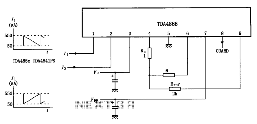
The TDA4866 test circuit operates with a positive supply voltage (VP) and a feedback voltage (VFB) in conjunction with a flyback circuit. The circuit responds to changes in the input signal, transitioning from one state to another. The input...
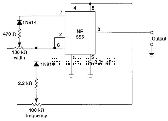
In this multivibrator circuit, frequency and pulse width can be separately controlled by using steering diodes (1N914) and two potentiometers. This multivibrator circuit utilizes steering diodes, specifically the 1N914 type, to enable independent control over both the frequency and pulse...
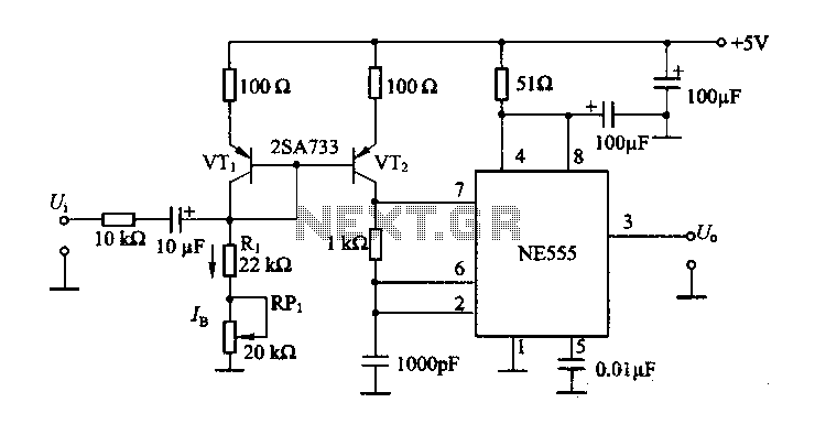
The circuit consists of a NE555 timer and a frequency modulation circuit that modifies the self-excited multivibrator NE555 by adjusting the charging current for frequency modulation. The components VT1 and VT2 form a current mirror circuit, which generates a...
The circuit depicted will automatically switch ON and OFF at night and morning, respectively. In this circuit, R1 can be adjusted to change the sensitivity. The operation of the circuit is straightforward. The Light Dependent Resistor (LDR) exhibits very...