
Class-A Power Amp

The power supply circuit described utilizes large capacitors to minimize hum, a common issue in audio amplifier designs. The significant capacitance is intended to smooth out voltage fluctuations, providing a stable DC output. However, the size and quality of these capacitors can lead to increased costs, which is a notable consideration for builders.
The "improved" Zen circuit introduces an inductor, or choke, in the power supply path. Inductors serve to further reduce ripple by opposing changes in current, thus enhancing the overall performance of the power supply. The use of an inductor can lead to a more refined audio output by mitigating high-frequency noise and hum, which is often a concern in audio applications.
It is important to note that while the addition of inductors can improve performance, they also contribute to the overall expense and complexity of the circuit. Availability of high-quality inductors can be limited, which may pose challenges for builders seeking to implement this design.
Moreover, the mention of increased capacitance in certain versions indicates a design evolution aimed at further improving performance. Doubling the capacitance can significantly enhance the power supply's ability to handle transient loads, providing a more robust and responsive audio experience.
The appeal of this design lies in its simplicity and stability, which are critical for many amplifier builders. The circuit's tolerance to variations in layout and components makes it accessible for both novice and experienced builders. Additionally, the sonic characteristics associated with this design, particularly in valve amplifiers, can attract enthusiasts seeking warm and rich audio reproduction.
Overall, this power supply design balances performance and cost, making it a viable option for audio amplifier applications while considering the trade-offs associated with component selection.The capacitors needed for the power supply are massive to try to get rid of hum, and massive means expensive. The "improved" Zen is a little better, since it uses an inductor (or choke) in the supply - obviously the hum drove someone mad.
Inductors are expensive too, and also hard to get, and the capacitance has been doubled in at least one version I have seen - ouch, this is seriously expensive! Well, actually I can see why it is popular. It satisfies the requirement of many amplifier builders, in that it is simple, stable, and very tolerant of layout and component variations. The sonic characteristics will also appeal to many, due to the valve-l 🔗 External reference
Related Circuits
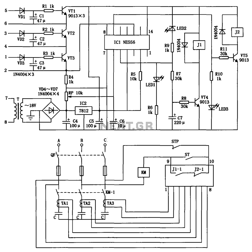
The circuit depicted is utilized in a power supply system to promptly disconnect the power supply in the event of an over-voltage condition during either the grid's on or off phase, thereby protecting the power capacitors. This circuit serves a...
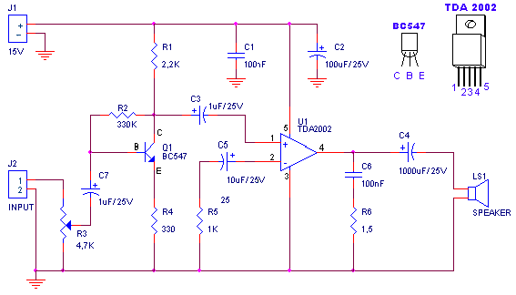
A small amplifier with nice characteristics: Tendency of catering: 15V. Force of expense: 4.2Wrms in the 4W. Minimal signal of entry: 94mVp-p with preamplifier, 0.65Vp-p without the preamplifier. More: Materially: R1=2.2kΩ R2=330kΩ R3=4.7kΩ logarithmic potentiometer R4=330Ω R5=1kΩ R6=1.5Ω C1,...
The first versions operated from ±15V supplies, featured bandwidths of 50 MHz, and delivered slew rates in the low hundreds of volts per microsecond. Today's fastest amplifiers run on ±5V supplies with bandwidths of 1.4 GHz and slew rates...
A 100 Ohm resistor connected to a 4.5 Volt supply (using three AA batteries) allows a current of 45 mA. However, at the upper end of the current sweep, the effective current will be significantly higher due to the...
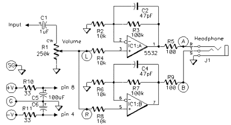
This simple amplifier is designed to add a headphone jack to equipment that does not have this feature. The Headphone Buffer circuit board is compact (1.2" x 1.4"), allowing it to fit into even the smallest spaces, and its...
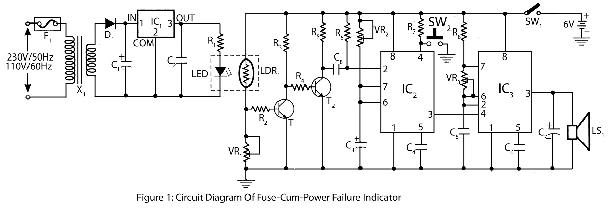
The Fuse Cum Power Failure Indicator utilizes a thermistor and a timer IC (NE555) in its circuit design. The circuit diagram includes a parts list for the fuse cum power failure indicator, which signals instances of power failure. The Fuse...