
Maze Robot
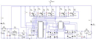
The electronic schematic for the robot features a double-decker PCB arrangement. The top layer hosts a PIC microcontroller, which serves as the central processing unit, managing inputs from the IR sensors and controlling motor outputs. The microcontroller is connected to the motor driver circuit, which is essential for controlling the motors' speed and direction based on the sensor inputs. The bottom layer of the PCB includes two voltage regulators to ensure stable voltage levels for the microcontroller and motor driver, as well as two switches for power control.
The IR sensors are strategically placed to detect obstacles and navigate the robot's path. The front sensor is crucial for immediate obstacle detection, while the side sensors help maintain the robot's orientation relative to walls. The signals from the sensors are fed into the microcontroller, which processes the data to determine the appropriate motor commands.
Power distribution is an important aspect of the design. The 9V battery provides power to the microcontroller and associated electronics, while the five 1.2V rechargeable batteries supply the motors. This dual power source ensures that the robot has sufficient energy for both processing and movement.
The chassis, constructed from aluminum, provides a sturdy frame for the robot, supporting the components and allowing for mobility. The design also considers weight distribution and balance to optimize performance during operation.
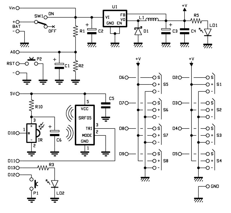
Overall, the schematic reflects a well-thought-out design aimed at achieving reliable performance in navigating simple environments, with room for further enhancements and optimizations in the programming and hardware configurations.After fail finishing the robot for the competition, I stopped updating my blog for a while. This is because I feel a bit disappointed for not be able to finish the robot in time. Today I am going to update the result of the entire work we hove done so far. The reason why we change the motor driver was because we found that the L293D can cause some short circuit that lighted up the other indicator LED that should not on. L293NE driver can work exactly the same as L293D without causing any of the stated problems; therefore we decide to change the motor driver. We also find out that the PWM could only be used in pin 16 and 17; therefore we change the connection of enable form the motor driver into these two pins.
We also find out that 9V battery cannot be use for a long time moreover; currents of 5 AAA batteries could not drive the motor. Therefore we decide to remove the 9 V batteries can add the AAA batteries. The previous design of the robot was also used for the competition purpose; therefore we were not bothered about the no-wall case condition.
The addition of 2 module IR sensors should be enough to solve the simple no-wall tract. With all of the changes, the circuit and circuit diagram of robot were also changed. With all of the changes made, the hardware and body of the robot are complete. The last thing to do is the programming. Programming of the robot is not an easy task since we cannot know whether the program is correct or not. The only way to know is to program it one by one and test it to the robot. Finding the correct threshold is also not an easy task. With all the hard work, we finally manage to fine the best threshold voltage. For the programming, we are trying our best to simplify the code. The left wall following algorithm is used as our first code. This algorithm set the priority to left. Whenever left is opened, the robot will turn to left. The flow chart of the main program is given bellow: With this flow chat, our robot can solve a simple maze.
Some optimization was still needed to get the best result. Until now we are still optimizing the code especially the function code. The PCB will be a double decker PCB with the top part consist of PIC and the circuit. The bottom part will consist of 2 voltage regulator circuit, 2 switches, motor driver and a pair of motors circuit. We are using 2 battery types that consist of a 9V square DC battery and 5 rechargeable batteries of 1.
2V. The 9 Volts battery will be used to drive the electronic circuit and the other for the motors. For the chases, we are using a plate of aluminum with a thickness of 2 mm. We are using 3 SHARP IR sensors. These sensors will be placed at front, right and left. At the front of the chases will be placed 2 batteries holder with 5 batteries attached to it. Two motors will be attached at the bottom of the chases. A 9 Volts battery will be placed at the back of the bottom chases. With all of that, the physical body of the robot is finished and ready to be built. The other problem that is needed to be done is for the programming. Right now we are still learning how to use the compiler and we hope that we will be able to finish the project on time. This week we were getting part of the component. We also have finalized our base body of the robot; therefore it was the time to build the PCB. I am the person in charge of building it. At first when I am building the PCB, I am thinking of using only one decker because the entire component can fit.
But after some consideration about the compactness of the PCB, we are changing our mind. At this time we are building the microprocessor component separate from other circuit. It will become a double decker PCB with top part of PIC since we may need to plug in and out frequently. The other part of the circuit will be built on the bottom PCB. This PCB couldn`t be finalized yet since we are still not sure about the other component we will get.
🔗 External reference
Related Circuits
The headlights and photo cells are oriented downward, leading to the visualization of the entire circuit as being inverted. The configuration utilizes three LEDs on each side. This choice is likely due to the inability to power three LEDs...
The objective of this post is to consolidate various robot designs and transform them into a new device featuring updated hardware and standardized software, specifically using Arduino, to enhance usability. These robots share three common elements: a mechanical structure,...
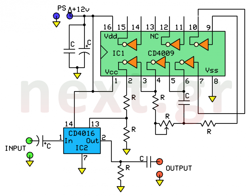
This system is a straightforward and dependable mechanism for processing human speech. Its primary function is to modify the tone of the human voice, making it sound artificial, similar to a robotic voice produced through artificial means. This circuit...

The head will be powered by servomotors and constructed from sheet plastic, metal, or plywood. A template for cutting the sheet material can be found at the end of this article. Download the template and compare the size of...
A robot that dances to music. It would be fascinating to have a small robot on your desk dancing to music from Fatboy Slim. Winamp provides an API for writing music visualization plug-ins. A plug-in was developed that sends...

A mobile-controlled robot is a mobile device that offers extensive wireless control capabilities to the robot, as long as the cell phone remains within signal range. The mobile-controlled robot operates through a wireless communication interface, typically utilizing Bluetooth or Wi-Fi...