
Differential Light
The described circuit utilizes a 1-inch square circuit board as the foundation for a light-sensing application. The variable resistor is strategically positioned at one edge for easy manual adjustment. The placement of the CdS cells at the opposite end, away from the edge, minimizes interference and facilitates better light detection.
The integration of the Lego brick serves as a housing for the circuit, where two pins are drilled near the center of one long side to secure the assembly. The four notches created at the base allow for the CdS cell leads to exit the brick without obstruction. This design ensures that the internal components of the Lego brick are completely removed, providing ample space for the circuit and preventing any unintended short circuits.
The connection of two short 3/16 rods to the circuit labeled RCX is crucial for interfacing with the Lego system. These rods are designed to fit into the holes of the top brick, ensuring that they do not interfere with the CdS cell leads. This careful consideration in design allows for seamless integration with the RCX, enabling it to function effectively as a light sensor.
When configured for light detection, the sensor will respond to variations in light intensity. The output readings will indicate a high value when one side is exposed to more light compared to the other side, which will register a low value. The adjustment of the variable resistor is essential for calibrating the system, allowing both sides to exhibit similar responses to light changes.
To enhance the directional sensitivity of the CdS cells, adjustments to their angle or the addition of a plastic barrier between them may be necessary. This modification can help focus the sensor's detection capabilities, improving its performance in distinguishing between light and dark environments.
CdS cells operate on the principle of photoconductivity, functioning as resistors that decrease their resistance in response to increased light exposure. This characteristic enables the creation of a simple yet effective light sensor, capable of detecting light and dark conditions by connecting a single CdS cell directly to the RCX for basic light sensing applications.Build circuit on a 1" square circuit board. Position the variable resister so that it can be adjusted from one of the edges. Attach the CdS cells at the other end but not at the edge. Drill out two pins next to the center of one of the long sides of a Lego brick. Make four notches at the base of that same side for the CdS cell leads to come out. R emove all of the insides of the brick. Solder two short 3/16 rods to wires that connect to the circuit where it is labeled RCX. Rods must be short enough to fit into the holes in the top brick and not touch the leads from the CdS cells. Plug this sensor into the RCX and set it for light. When one side has more light it will read high, when the other side has more light it will read low. Adjust the resister to get each side to react about the same way. You might want to adjust the angle of your cells or glue a piece of plastic between them to get it more directional.
CdS cells are simply resisters that loose resistance as more light hits it. So you could make a light sensor that detects just light and dark by hooking up one cell directly to the RCX. 🔗 External reference
Related Circuits
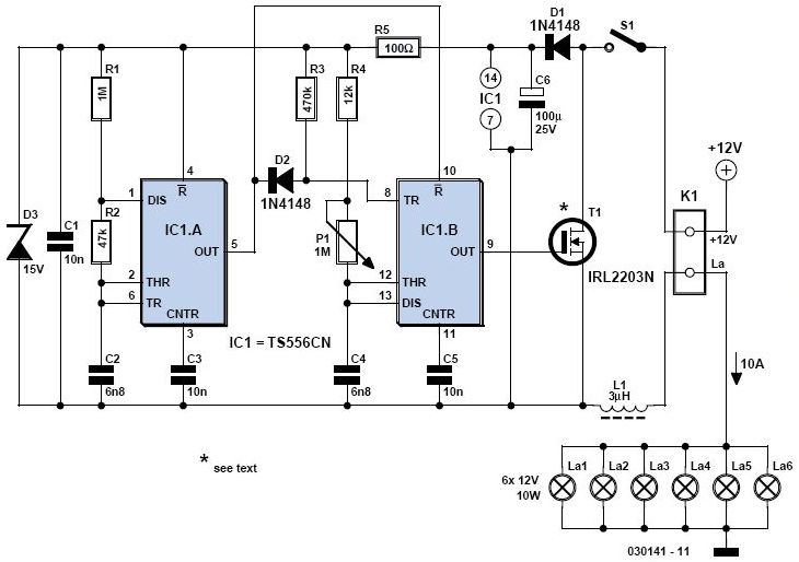
A light dimmer is quite uncommon in a caravan or on a boat. This document outlines how to create one, allowing for mood adjustment when needed. A light dimmer circuit is an essential component for enhancing the ambiance in confined...
The 555 circuit described is a flashing bicycle light powered by four C, D, or AA cells (6 volts). It features two sets of 20 LEDs that flash alternately at approximately 4.7 cycles per second, utilizing the specified RC...
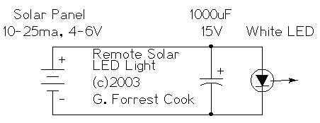
The remote solar powered LED light takes advantage of the current limited nature of solar photovoltaic cells. If light shines on the solar array, current will flow through the circuit. For a typical size of solar cell, there is...
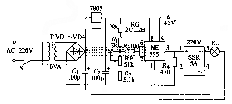
The NE555 time base circuit with an AC solid-state relay (SSR) can function as an automatic light switch circuit. The circuit diagram illustrates that during the day, the incandescent light is turned off due to the influence of the...

This is a simple automatic light switch circuit designed for bedrooms. After construction, connect the input terminals of this circuit in parallel to the existing light fixture. The automatic light switch circuit operates using a photoresistor (LDR) and a transistor...
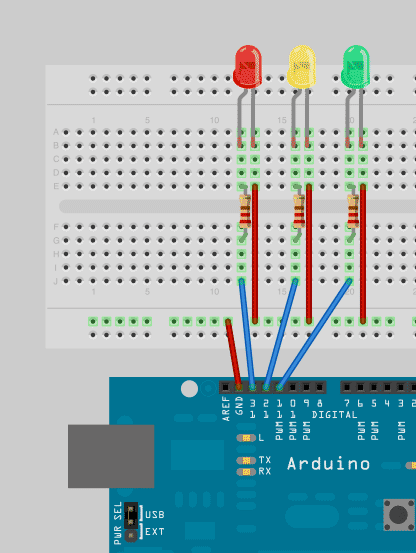
To enhance Arduino programming skills, developing a traffic light controller serves as an excellent practice project. The traffic light controller project involves designing a circuit that simulates the operation of a traffic light system, typically consisting of red, yellow, and...