
Function Generator
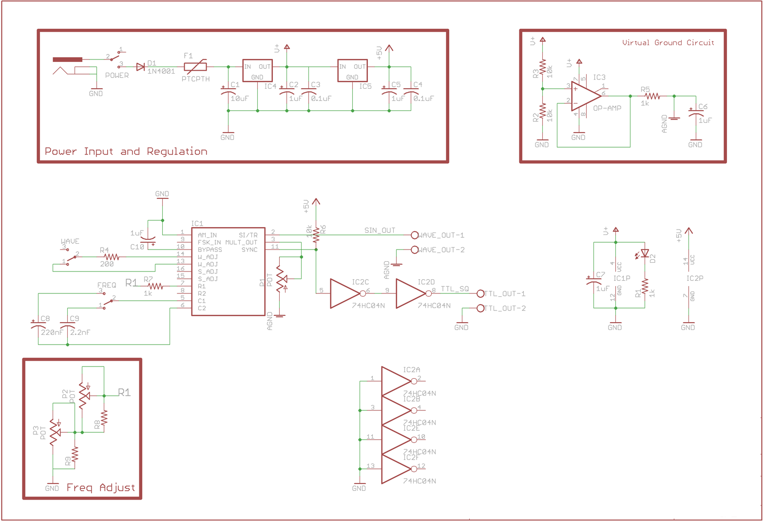
The buffered virtual ground circuit plays a critical role in signal processing applications by providing a stable reference point for the output waveforms. The use of an LM741 or LM318 operational amplifier ensures that the virtual ground is maintained accurately, allowing for precise waveform generation. The virtual ground voltage is typically set to half of the input voltage, which effectively allows the sine and triangle waves to oscillate symmetrically around 0V, making the output suitable for various applications such as audio signal processing or modulation tasks.
The amplitude and frequency adjustment potentiometers facilitate user control over the generated waveforms, enabling fine-tuning of the output characteristics to meet specific requirements. The inclusion of these adjustable components directly on the board enhances usability and accessibility for the operator.
Moreover, the ON/OFF switch provides a straightforward means of powering the circuit, ensuring that the system can be easily activated or deactivated as needed. The waveform selector switch allows the user to choose between different waveform outputs, such as sine or triangle waves, thereby increasing the versatility of the circuit. The frequency range switch further extends the functionality by enabling the selection of different frequency bands, allowing for a broader range of signal generation.
Overall, this design is well-suited for applications requiring variable waveform generation, with an emphasis on user-friendly controls and robust performance.The design includes a buffered virtual ground circuit provided by an LM741, LM318 or similar Op Amp, which sets a fixed voltage half way between the input voltage and ground. This is then used as the virtual ground for the sine and triangle wave outputs from the "WAVE_OUT" connector, providing an output centred around 0V.
The amplitude and frequen cy adjustment pots are mounted on the board for easy adjustment. An ON/OFF switch, Waveform selector switch and Frequency range switch are also mounted on the board. 🔗 External reference
Related Circuits
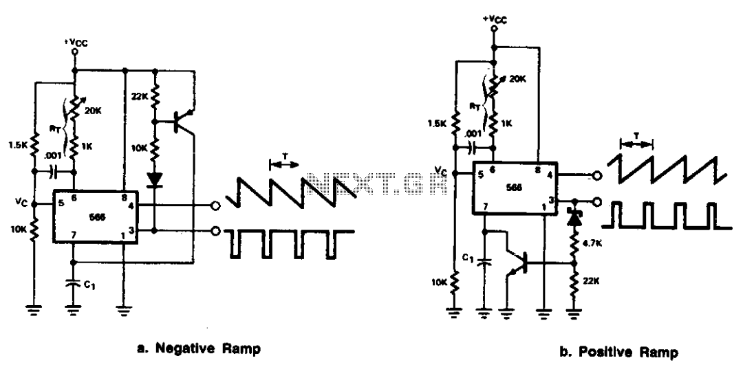
The 566 can be configured as either a positive or negative ramp generator. In the positive ramp generator configuration, the external transistor controlled by the output at Pin 3 quickly discharges capacitor C1 at the conclusion of the charging...
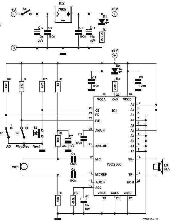
The voice generator scheme schematic diagram utilizes the ISD2500 series of chip-coders from Winbond, which encompasses all necessary components for recording and playback of voice messages. These chips feature microphone preamps with Automatic Gain Control (AGC), allowing compatibility with...
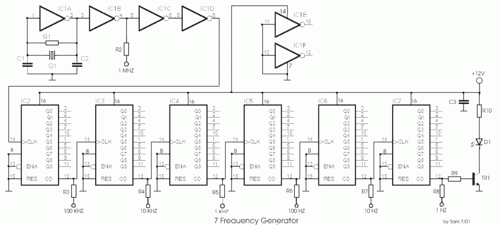
The circuit was designed to create a frequency generator that consists of seven steps during operation. It includes a crystal oscillator, which is an electronic circuit made of... The frequency generator circuit operates through a series of seven distinct steps,...

This circuit design generates a stable 1 kHz sine wave using an inverted Wien bridge configuration with components C1-R3 and C2-R4. It offers a variable output, low distortion, and low output impedance to ensure good overload capability. The circuit...
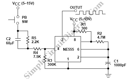
Square wave tone bursts are generated by pressing the pushbutton. The duration of these bursts is determined by how long the voltage at Pin 4 exceeds a specified threshold. The circuit described involves a square wave generator that produces tone...

The Wien bridge oscillator generates frequencies of 1 Hz and from 2 to 20 Hz in 2 Hz increments. The maximum output amplitude is 3 volts RMS or 8 volts peak-to-peak. A potentiometer and switch attenuator enable the output...