
Home Built Battery Charger
The described battery charger is a robust solution for charging 12-volt battery banks, particularly in scenarios where the batteries are deeply discharged. The charger utilizes a repurposed 1000-watt inverter casing, which enhances portability and provides structural integrity. The design incorporates a high-current output capability, initially providing a charging current of 60 amps, which is suitable for quick battery recovery. As the batteries approach their full charge, the current tapers to 10 amps, which is a common charging strategy to prevent overcharging and extend battery life.
The construction of the bridge rectifier is a notable aspect of this design. By utilizing nine car alternator diodes in parallel, the system compensates for the lack of a commercially available high-capacity bridge rectifier. This method, while effective, introduces complexity and potential thermal management challenges, as the diodes will generate heat during operation. The use of a heat sink and a substantial bus bar made of unistrut demonstrates an effective approach to managing heat dissipation, ensuring safe and reliable operation.
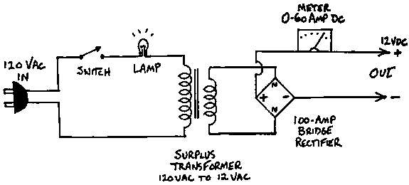
For individuals considering similar projects, it is advisable to procure a bridge rectifier rated for at least 70 amps to streamline the assembly process and enhance reliability. This change would eliminate the need for the intricate diode assembly while maintaining the system's performance. Additionally, the availability of large bridge rectifiers on the market provides an alternative for those seeking to simplify their designs without compromising functionality. The wiring diagram accompanying the charger will serve as a valuable reference for anyone looking to replicate or modify this charging solution.The battery charger pictured here is a real beast. It will dump 60 amps into a 12 volt battery bank that is low, and will taper down to about 10 amps charging current as the batteries fill. Total cost, $20! The basis of this charger is dead 1000 watt inverter from Heart. A lightning strike fried the electronics in this unit, but the transformer wa s intact. The owner elected to replace it with a new model, and we picked it up for $20. The inverter case made a handy case for the charger, too, because of the handles. The whole unit weighs over 50 pounds. At the time, we did not have a large enough bridge rectifier available, so we built one out of 9 car alternator doides connected in parallel to a heat sink. The bridge gets hot in use, but the diode bus bar is a peice of unistrut that`s massive enough to dissipate the heat produced.
Here is the wiring diagram for the charger. Buying a bridge rectifier big enough to handle 70 amps would simplify construction. the home built diode bridge was the most complicated part of the project. Check our products page, we sometimes have large bridge rectifiers for sale. 🔗 External reference
Related Circuits
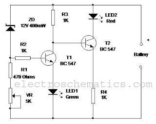
This circuit monitors the charging process of a 12 Volt Lead Acid or Tubular battery. The LED status indicates whether the battery is charging and signals when it reaches a full charge. It can be integrated into various battery...
This simple charger utilizes a single transistor as a constant current source. The voltage across a pair of 1N4148 diodes biases the base of the BD140 medium power transistor. The base-emitter voltage of the transistor and the forward voltage...
The circuit described here provides around 180mA current at 5.6V and protects the mobile phone from unexpected voltage fluctuations that develop on the mains line. So the charger can be left on over night to replenish the battery charge....
Below is a comparator circuit that can measure the voltage of a car battery in steps of 1 volt. The voltage indication is achieved through comparison. The comparator circuit designed for measuring the voltage of a car battery utilizes an...
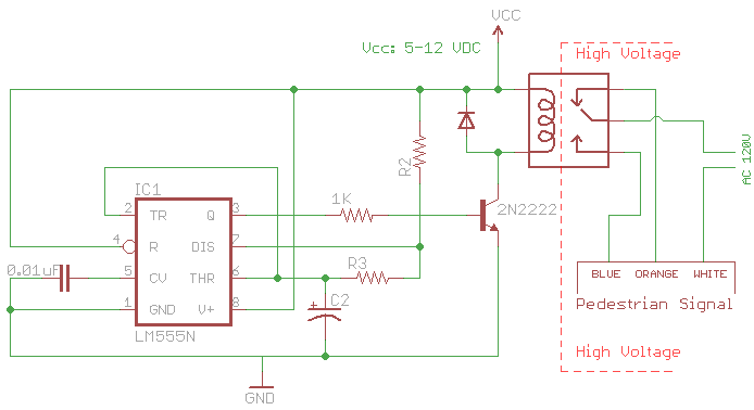
The signal consists of three wires: common, "walk," and "don't walk." This document outlines the operation of the unit's countdown feature. The information and examples provided here are applicable to other models and brands of signals. The signal was...
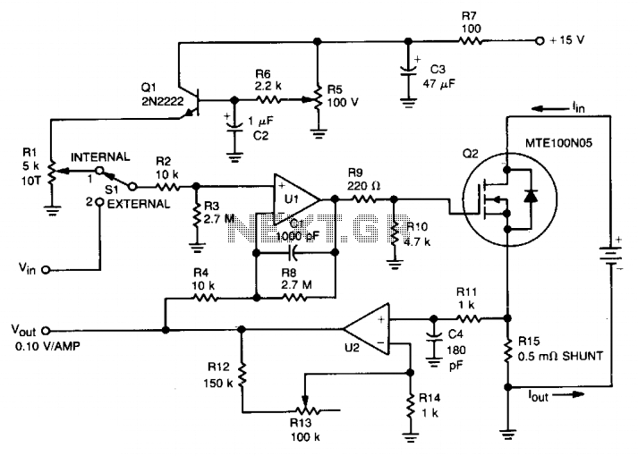
This circuit was designed for testing fuel cells, but it could also be used for testing batteries under a constant current load. It provides a dynamic, constant current load, eliminating the need to manually adjust the load to maintain...
Warning: include(partials/cookie-banner.php): Failed to open stream: Permission denied in /var/www/html/nextgr/view-circuit.php on line 713
Warning: include(): Failed opening 'partials/cookie-banner.php' for inclusion (include_path='.:/usr/share/php') in /var/www/html/nextgr/view-circuit.php on line 713