
How to test a triac

To conduct a thorough assessment of a triac using a multimeter, the following steps can be implemented. The multimeter should first be set to a high resistance mode, typically around 100K ohms. This setting helps to measure the off-state resistance of the triac. The positive lead is connected to the MT1 terminal, while the negative lead is connected to the MT2 terminal. In this configuration, the expected reading on the multimeter should be a high resistance value, which indicates that the triac is not conducting in its off state.
Subsequently, the multimeter should be switched to a low resistance mode. In this mode, connect the positive lead to the MT1 terminal and the gate of the triac, and the negative lead to the MT2 terminal. A low resistance reading in this configuration indicates that the triac is now in the ON state, confirming that it is functioning correctly.
It is important to note that this testing method may not be suitable for all triacs, particularly those that require a high gate voltage and current to trigger. For these cases, an alternative testing method can be employed, which involves a simple circuit designed to demonstrate the operational characteristics of a triac.
In this alternative method, the triac is connected to a basic circuit as depicted in a circuit diagram. The circuit includes a lamp and two switches: S1 (a push button) and S2 (a toggle switch). Initially, switch S2 is turned ON, and the lamp should remain off, indicating that the triac is not conducting. When the push button switch S1 is pressed, the lamp should light up, demonstrating that the triac is now in the ON state. Upon releasing the push button, the lamp should extinguish, confirming the triac's ability to switch on and off correctly.
If both testing methods yield positive results, it can be confidently concluded that the triac is in good health and capable of performing its intended function in a circuit.A multimeter can be used to test the health of a triac. First put the multimeter selector switch in a high resistance mode (say 100K), then connect the positive lead of multimeter to the MT1 terminal of triac and negative lead to the MT2 terminal of triac (there is no problem if you reverse the connection). The multimeter will show a high resistanc e reading (open circuit). Now put the selector switch to a low resistance mode, connect the MT1 and gate to positive lead and MT2 to negative lead. The multimeter will now show a low resistance reading (indicating the switch ON). If the above tests are positive then we can assume that the triac is healthy. Anyway this test is not applicable triacs that require high gate voltage and current for triggering. This is another approach for testing a triac. Almost all type of triacs can be tested using this circuit. This circuit is nothing but a simple arrangement to demonstrate the elementary action of a triac. Connect triac to the circuit as shown in circuit diagram and switch S2 ON. The lamp must not glow. Now press the push button switch S1. The lamp must glow indicating the switching ON of triac. When you release the push button, you can see the lamp extinguishing. If the above tests are positive you can assume that the triac is healthy. 🔗 External reference
Related Circuits
The TRIAC is a three-terminal device that operates similarly to the SCR. Unlike the SCR, which conducts current flow during only one alternation of an AC cycle, the TRIAC allows current to flow during both alternations. The schematic symbols...

The JFET Pierce oscillator is designed to test any crystal within a frequency range of 50 kHz to 25 MHz, accommodating the upper frequency limit of fundamental-mode crystals without the need for tuning. It is capable of driving a...
The Testatika design, based on the Pidgeon/Wimshurst machine, represents one type of electrostatic generator that can be used to construct this system. Since the early 1900s, such power generators have significantly evolved in terms of sophistication and power output....

This low-current audio continuity tester indicates the unknown resistance value by the frequency of the audio tone. A high tone indicates a low resistance, while a tone of a few pulses per second indicates a resistance as high as...
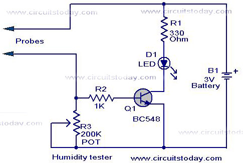
A simple humidity tester circuit using only an LED, a transistor, and a few resistors is explained with a clear circuit schematic. The humidity tester circuit is designed to provide a visual indication of humidity levels using basic electronic components....
This circuit employs the widely used and easily accessible LM3914 integrated circuit (IC). The LM3914 is straightforward to operate, does not require external voltage regulators due to its built-in voltage regulation, and can be powered by a variety of...