
Infrared Remote Control Tester
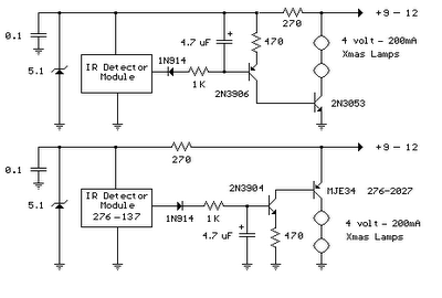
The infrared detector module GP1U52X is designed to interface seamlessly with various remote control systems, allowing for the detection and processing of infrared signals. The module outputs a TTL-compatible pulse train, which is essential for digital signal processing in applications such as remote control receivers. The circuit is structured to ensure that the output remains low until an infrared signal is detected, at which point the pulse train is generated, indicating activity.
The 4.7 µF capacitor plays a crucial role in the timing aspect of the circuit, charging quickly upon receiving a pulse and discharging gradually to maintain the output state. This behavior is particularly useful in applications where a brief illumination of lights is desired, such as in decorative lighting setups. The choice of transistors (2N3904 or 2N3906) for the initial amplification stage ensures that the circuit can handle the necessary current levels to drive larger output transistors (2N3053 or MJE34), which are capable of supplying sufficient current for lighting applications.
The circuit's flexibility is highlighted by its ability to operate over a range of input voltages, accommodating various power sources, including wall transformers and batteries. The inclusion of a filtering capacitor enhances stability, particularly in scenarios where the power supply may not provide a clean output. The option to replace the light bulbs with LEDs further extends the circuit's versatility, allowing for energy-efficient operation while still providing adequate illumination.
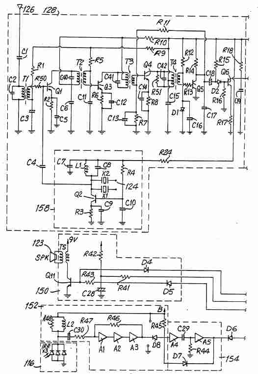
Overall, this infrared detector circuit exemplifies a robust design that can be adapted for various applications, from simple remote control functions to more complex lighting solutions. Its ability to operate with different components and power sources makes it a valuable addition to any electronics project involving infrared signal detection and processing.The infrared detector module (GP1U52X) (Radio Shack 276-137) provides a 5 volt TTL pulse train corresponding to the digital code to the button of the remote control. In the lower circuit, the module output normally low a signal and a positive going pulse train whena signal is present.
Other detector modules that an inverted output is in the upper drawing, which showed type I, but I do not have the part number, I think from a video recorder. The pulse sequence, the digital codes of special keys is available with information directly from the manufacturer. Since the pulse train occurs, the 4. 7uF capacitor charges to approximately 3 volts and the capacitor voltage minus a diode drop appears above the 470-ohm resistor, a collector current of the 2N3904 or 2N3906 about 5 milliamperes.
The collector current of the first stage flows into the base of the output transistor (2N3053 or MJE34), which provides about 250 mA in direction. If the pulse train ends of the capacitor discharged slowly through the bottom of the first transistor stage left, the Christmas tree lights for about 1 second.
The little Christmas lights will operate over a wide voltage range, so you can use bulbs from almost any string, but spheres of short strings (35 or less) will probably run longer at least 5 volts. The circuit can be a small 9-12 volt DC, 250 mA wall transformer or operated higher. It can also be an additional 1000 uF capacitor filter on the DC output if the wall transformer no built-in capacitor.
For use with a 9 volt battery, the light bulbs are replaced by a simple LED and 680 Ohm resistor and the output transistors by low signal transistor (2N3904 or 2N3906) can be replaced. The total power is about 25 mA with LED lights, standby and 15 mA when the LED should be. 🔗 External reference
Related Circuits
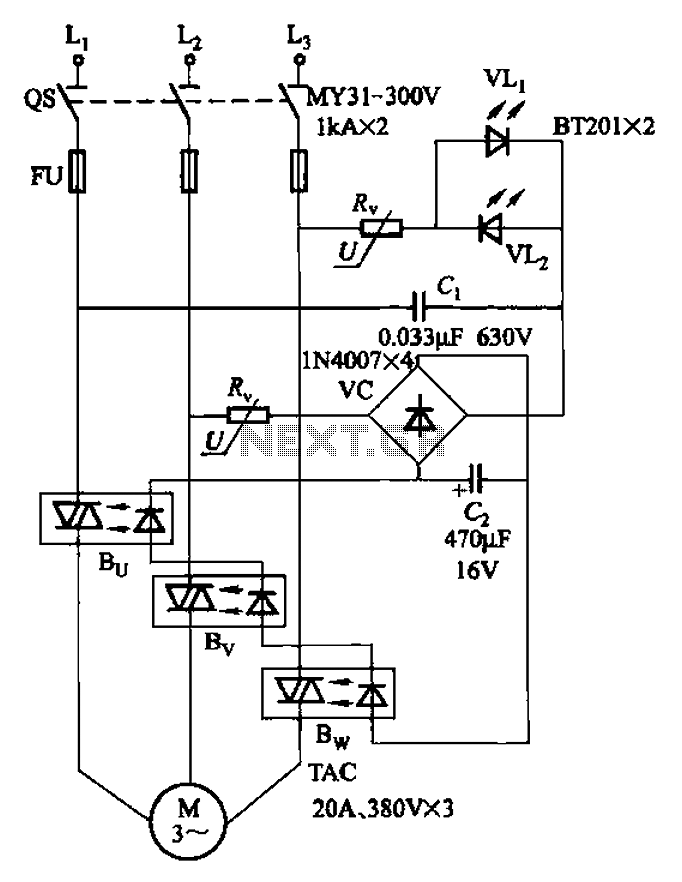
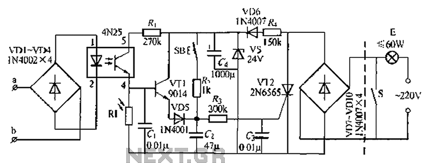
The circuit depicted in Figure 3-93 is integrated with an optical phase sequence protection relay. The circuit in question is designed to provide phase sequence protection using an optical relay mechanism. Optical phase sequence protection relays are crucial in applications...
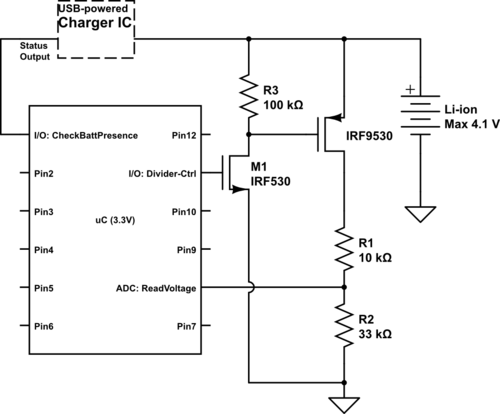
Currently using the PIC24FJ128GA010, there is a plan to utilize an Input/Output port to connect a 4.2 V LiPo battery and monitor the voltage to ensure it does not drop below 3.7 V. It is advised to avoid digital...
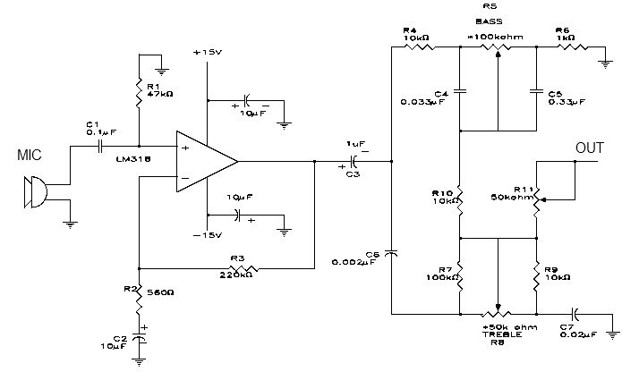
This electronic project is a simple microphone preamplifier based on the LM318 operational amplifier. The LM318 is configured as a standard non-inverting amplifier. Resistor R1 provides a ground reference for the bias current of the non-inverting input. The combination...
Multiple unit radio control: How to create a multi-unit radio control system. A multi-unit radio control system allows for the simultaneous operation of multiple devices or units using a single remote control transmitter. This system is commonly used in various...
An automatic light system is integrated with a telephone block system. When the phone rings, the owner is prompted to pick up the handset or pull a lever, causing the lamp to light up. If there is no contact...
A timing and counting circuit utilizing integrated circuit chips with seven-segment LED displays is employed to show the current lap time, previous lap time, and total number of laps completed on a 1/64th-scale slot car racetrack. A switch activated...