
Infrared transmitter
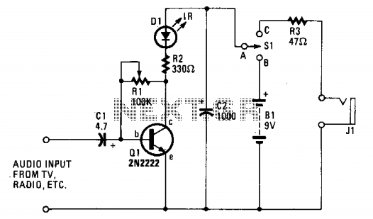
The one-transistor infrared (IR) transmitter circuit operates by modulating the audio signal onto an infrared light beam, allowing for wireless transmission of sound. The core component of this circuit is a single transistor, which serves as the main amplification and modulation element.
The circuit typically includes a few key components: a transistor (such as the 2N3904), an IR LED for transmitting the modulated signal, a resistor to limit the current through the LED, and capacitors to filter the power supply and stabilize the operation. The audio source is connected to the base of the transistor, which modulates the current flowing through the IR LED according to the audio signal.
When the audio signal is applied, the transistor switches on and off rapidly, causing the IR LED to emit pulses of infrared light that correspond to the audio waveform. The IR light can then be received by an appropriate IR receiver, which demodulates the signal back into audio, allowing for playback through speakers or headphones.
This circuit is particularly advantageous for its simplicity and low component count, making it accessible for hobbyists and educational projects. It is suitable for applications where short-range wireless audio transmission is required, such as in remote control systems or basic wireless audio setups.The ultra-simple one-transistor, IR transmitter shown is designed to transmit the sound from any 8 or 16 ohm audio source, such as a TV, radio, or tape recorder on an infrared beam of light. Easy to make it! 🔗 External reference
Related Circuits
Here are the schematics for infrared remotes. This remote transmits a tone using an infrared LED. This tone is decoded by the receiver. Since the receiver only switches when it "hears" the tone, there are no accidental activations. The schematic...

According to the note on the schematic, IC-2 is a 74HC74 TTL chip. Refer to the data sheet for details regarding pins 7 and 14. The note for IC-3, located lower on the schematic, indicates it is an AC...

The infrared (IR) toggle switch project described here aims to provide a control mechanism for electrical appliances that lack remote operation features. The goal is to construct a black box where users can plug in their 120V AC appliance...

This circuit is a long-range, highly stable, harmonic-free FM transmitter designed for FM frequencies between 88 and 108 MHz. With an appropriate antenna, it can cover a range of up to 5 km. The circuit features a stable oscillator...
The site features several low-power transmitters, but until now, there has been no receiver. This circuit can be utilized to scan an area or room, indicating whether a surveillance device is active. The challenge in creating an effective detector...

For the regulation it needs a voltmeter (with needle better) and charge 50W/5W. Connect charge 50W in the place of aerial, with the voltmeter in the exit voltmeter. Be supplied the transmitter with + 12V. It will be supposed...