
IR Link
Or cover the opening using a small piece of dark transparent plastic. Part of the display panel from a scrap VCR is ideal. Position the unit out of direct light and avoid reflective surfaces. If all else fails, adjust VR1 to reduce sensitivity. What you are aiming for is to ensure that in standby mode Q2 remains switched off so that C2 retains its charge. If unwanted radiation does reach the receiver it will not result in a large output current. C2 simply discharges and the circuit shuts down. When the source of the unwanted radiation is removed the unit may be reset by interrupting the power supply for a few seconds or by pushing the (optional) reset button.
If you do neither then it will reset itself after about an hour when C2 has recharged through R7. With two receiver diodes wired in parallel, the operating range is up to about 1 meter. The exact distance depends on the remote you are using and on the position of VR1 (start by setting it about halfway). Correctly focused, a plastic lens from a small magnifying glass will extend the distance. I used the high gain version of the BC337 because that was what I had available. However, the only transistor whose gain is likely to be important is the BC547C. For the infrared emitter I used a TIL38 (Maplin YH70M) at the end of 12 meters of alarm cable. However, the diode from a scrap remote control should be worth trying also. Two diodes wired in series will give improved output performance. The circuit was designed with a small 9-volt alkaline battery in mind (PP3, MN1604, 6LR61) but the prototype worked well at 6-volts using four AA batteries.
The standby current was too small to measure reliably. An earphone socket makes the unit portable; so it can be used in more than one room. If you can obtain the style of socket in the diagram (Maplin HF82D), its normally closed switch can be converted to a normally open switch by releasing the inner contact as shown. This means that it will act as an on/off switch when you unplug the lead; and because it allows you to interrupt the power supply, there is no need for a reset button.
🔗 External reference
Related Circuits

An astable multivibrator is an electronic configuration that generates continuous alternating high and low pulses from two outputs operating in tandem. The IC 4093 consists of four individual NAND gates in one package, specifically Schmitt trigger types, which provide...
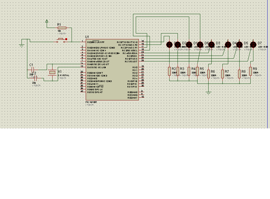
The code in mikroC PRO for the PIC16F887 microcontroller is designed to operate with an 8.000 MHz clock frequency on a Microchip 44-pin demo board. The routines have been developed using HITECH C, but the focus is on utilizing...
This circuit represents a unique blinker indicator designed for use in vehicles or models. The running-light display moves either to the left or the right, depending on which directional signal is activated. This feature is particularly appealing for those...

When the preset is set to its maximum, the LED flashes at a rate of approximately once every half second. This rate can be increased by raising the capacitor value from 10µF to a higher value. For instance, if...
A very simple LED flasher circuit. With HT-2014L the circuit produces 1 flash per second and the HT-2014M produces 2 flashes per second. The LED flasher circuit is designed to provide a visual indication through intermittent illumination of an LED....
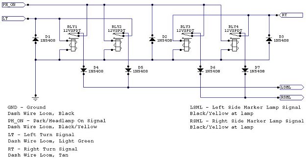
The Neon model has inboard mounted turn signals, which are not visible from the side. Typically, manufacturers mount a second light that is visible from the side or configure the side markers to blink, as seen in the 9x...