
IR Remote Control Switch
The circuit utilizes a relay as the primary switching element, enabling the control of high-power devices through low-power signals. The key components of the circuit include a relay, a power supply, a transistor, and a remote control receiver module.
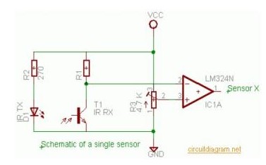
The operation begins with the remote control, which sends an infrared (IR) signal to the receiver module. The receiver module is connected to a transistor that acts as a switch. When the IR signal is detected, the receiver outputs a signal that turns on the transistor. This allows current to flow through the relay coil, energizing the relay and closing its contacts. Consequently, the connected electrical device is powered on.
To turn off the device, the remote control sends another signal, which is again received by the module. This signal deactivates the transistor, cutting off the current to the relay coil. As a result, the relay opens its contacts, disconnecting the power supply to the device.
The circuit can be powered using a standard AC or DC power supply, depending on the relay specifications. It is important to ensure that the relay used can handle the voltage and current requirements of the connected device. Additionally, proper isolation techniques should be employed to protect the low-voltage components from high-voltage spikes that may occur when switching inductive loads.
This remote control switching circuit is versatile and can be used for various applications, including controlling lights, fans, and other household appliances, providing convenience and energy efficiency.Today we are going to explain about a simple circuit which is used to switch on/off any electrical device remotely through a relay using the normal TV/VCR.. 🔗 External reference
Related Circuits
An infrared wired repeater circuit is designed to control appliances from a remote location. Parts List: R1: 1k Resistor (1), R2: 3.3k Resistor (1), R3: 10k Resistor (1). The infrared wired repeater circuit serves as an interface for controlling various...
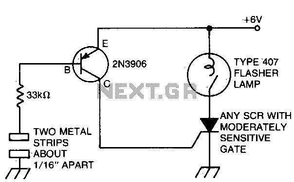
The battery-powered light activates with ease, remaining illuminated for a few seconds before automatically shutting off. The circuit is engaged when a finger bridges the gap between two metal strips, approximately 1/16 inch apart. Sufficient current flows through the...
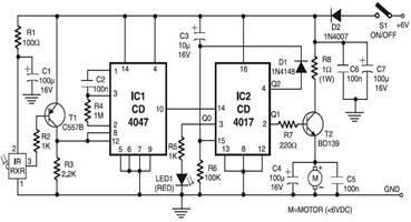
The following circuit illustrates an infrared toy car motor controller. This circuit is based on the 4047 and 4017 integrated circuits (ICs). Features: 16V. The infrared toy car motor controller circuit utilizes two primary integrated circuits, the 4047 and the...
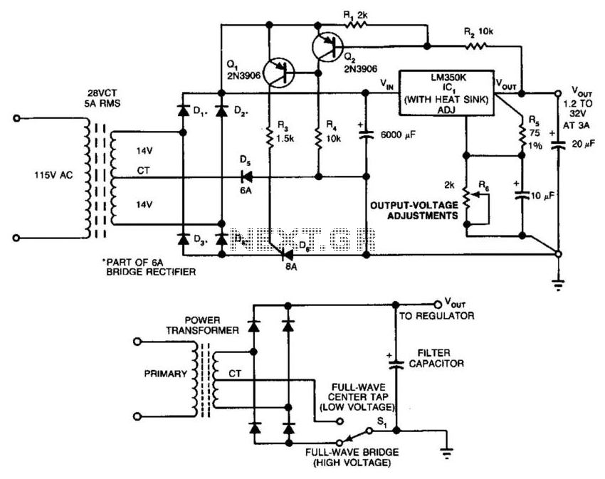
In this circuit, a full-wave bridge is switched to a full-wave center tap to reduce regulator dissipation. SCR D6 switches between configurations. When D6 is off, the circuit is an FWCT rectifier using D1, D2, and D5. It applies...
This AC drill speed controller circuit schematic allows for the control of the drilling speed of a borer or drilling machine. This project is based on the principle that... The AC drill speed controller circuit is designed to modulate the...
This simple AVR programmer is capable of transferring hex programs to most ATMEL AVR microcontrollers. It is more reliable than many other simple AVR programmers available and can be constructed in a very short amount of time. This programmer...
Warning: include(partials/cookie-banner.php): Failed to open stream: Permission denied in /var/www/html/nextgr/view-circuit.php on line 713
Warning: include(): Failed opening 'partials/cookie-banner.php' for inclusion (include_path='.:/usr/share/php') in /var/www/html/nextgr/view-circuit.php on line 713