
Light Dimmer
The light dimmer circuit utilizing a 555 timer oscillator is designed to modulate the brightness of a connected lamp by adjusting the duty cycle of the output signal. The 555 timer operates in astable mode, generating a continuous square wave signal. This signal is then used to control a power electronic component, such as a triac, which regulates the power delivered to the lamp.
In the circuit, the 555 timer is configured with resistors and a capacitor that determine the frequency and duty cycle of the output waveform. The resistors set the charge and discharge times of the capacitor, allowing for control over the on and off durations of the lamp. The triac is triggered by the output from the 555 timer, allowing current to flow to the lamp when the triac is in the conducting state. By varying the resistance in the timing circuit, the light intensity can be smoothly adjusted, providing a range of brightness levels.
When implementing this circuit, it is important to ensure that all components are rated for the appropriate voltage and current levels to prevent damage or failure. Additionally, heat dissipation should be considered, as the triac may generate heat during operation. Adequate heat sinking or cooling methods may be necessary to maintain reliable operation.
Safety is paramount when working with mains voltage circuits. Proper insulation, secure connections, and adherence to electrical codes are essential to prevent electrical hazards. It is recommended to use enclosures for the circuit to prevent accidental contact with live components. Always refer to the manufacturer's specifications and guidelines for safe operation and installation practices.The concept behind the light dimmer is to control the voltage to the light lamp or any source. Light dimmers regulate the voltage to the source they are connected to. This regulation of voltage increases or decreases the light intensity. Light dimmers first appeared in the market around 1960s. In the beginning light dimmers used adjustable power resistors and transformers to regulate the voltage. The use of transformers in early light dimmers did not prove a success. The light dimmers produced poor results and were expensive and non durable. As the electronics made progrss over the time, new methods and components were invented. Thyristors and triacs came to teh market and because of these components, new modern light dimmers were invented which were cheap, durable and gave better results. Today, modern light dimmer manufacturers use thyristors and triacs in their construction. Light dimmers are very inexpensive and ranges from $5-$30 depending on the model and manufacturer. Light dimmers are the best replacements for regular light switches because of there many features like durable, easy installation and different attractive styles.
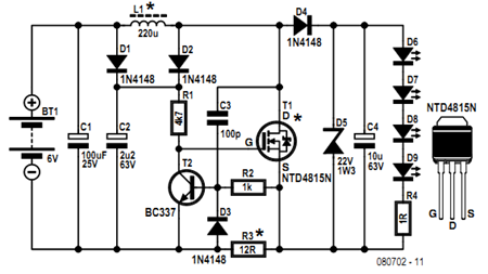
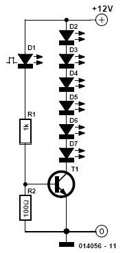
Light dimmers have the following important features. We can build our own light dimmer circuit for fun or for our science project. Following is the circuit diagram of a 12V light dimmer switch. The circuit is constructed with 555 time oscillators and resistors. Two different circuits are shown for light dimmer. One shows the circuit when lamp is connected to the positive connection and the other connected to the negative side of the supply. The circuit uses the principle of capacitors which is when charged produces short positive interval and long negative interval which dims the intensity of the light.
Light dimmers are connected to mains, therefore safety precautions should be taken during installation of light dimmer. During installation, it should be made sure that no part of the circuit can be touched. Always look in the instruction manual for safety measures where it says `Safety Instructions for light dimmer`
🔗 External reference
Related Circuits
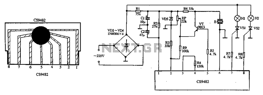
The CS9482 integrated circuit fabrication is demonstrated with a holiday lights circuit. The CS9482 chip includes a 4.1V voltage regulator circuit; therefore, while the external circuit does not need to be regulated, if the voltage exceeds 4V, a current-limiting...
The mains supply can be conveniently reduced with no heat dissipation by the reactance of C1; then rectified by D1 (1N4007) and D2 (1N4007) and clamped to 24V. The circuit operates by utilizing the reactance of capacitor C1 to reduce...
The wireless light switch circuit described here requires no physical contact for operating the appliance. You just need to move your hand between the infrared LED (IR LED1) and the phototransistor (T1). The infrared rays transmitted by IR LED1...
Before getting started, an acknowledgment is due. The circuit presented here employs an innovative method of controlling a flyback converter using the voltage developed across a current-sensing resistor. This approach was published by Andrew Armstrong in the July 1992...
This simple and inexpensive circuit is not limited to Christmas. It consists of two resistors, a small-signal transistor such as a BC547, one flashing LED, and a string of standard LEDs. The flashing LED functions as an oscillator, turning...

The electronic schematic of the Light Detector Robot can be divided into three main components: the sensor, the microcontroller, and the DC motor driver. The light sensor utilized in this design is a Light Dependent Resistor (LDR), which alters...