
Line-Following Mini-Tank - Schematic

The schematic can be divided into three primary sections, each serving a specific function essential for the overall operation of the system.
The sensor circuitry is crucial as it interfaces with an accelerometer, which measures acceleration forces. This data is converted into a digital format by the A/D converters, allowing for precise processing of sensor information. The design of this section must ensure minimal noise interference to maintain accurate readings, which may involve the use of filtering capacitors and proper grounding techniques.
The power circuit is designed to provide stable voltage levels necessary for the operation of all components. The inclusion of a 3.7V rechargeable lithium battery ensures that the system can operate independently without external power. The 7805 voltage regulator is employed to step down the voltage to +5V, which is essential for powering digital components such as the A/D converters and microcontrollers. The On/Off switch allows for convenient control of the entire system, ensuring energy conservation when the device is not in use.
The motor circuit plays a pivotal role in executing the physical actions of the robot. With two 3V motors, the design allows for moderate-speed movement. The diode in the circuit serves a dual purpose: it not only protects the circuit from back EMF generated by the motors when they are turned off but also reduces the voltage supplied to the motors, effectively controlling their speed.
The integration of the IR emitter LED and phototransistor is vital for surface detection. The IR emitter projects light onto surfaces, and the phototransistor detects the intensity of the reflected light, allowing the system to distinguish between different colors or surfaces. This feedback is essential for the robot's navigation and operational capabilities.
Finally, the ASIC logic provides a compact and efficient means of processing sensor data. It interprets the signals from the sensor circuitry and determines the appropriate motor actions based on predefined logic. This allows for real-time response to environmental changes, enhancing the robot's functionality and adaptability.
Overall, the schematic is a well-coordinated assembly of components that work together to create an intelligent robotic system capable of responding to its environment effectively.The Schematic has three main parts to it. The Sensor Circuitry where the accelerometer is wired up to the A/D converters. The second part is the power circuit where we have the On/Off switch, the 3. 7v battery & +5v 7805 Voltage Regualtor. The 3rd part of the circuit is the 3 7-Segment LEDs. The motor circuit controls the motors depending on the s ensor data that comes in through the `analog brain` circuit. The two motors are 3v and can move moderatley fast. The diode that connects the motors to the battery reduces the voltage at the motors which slows them down a little bit. The IR Emitter LED and Phototransistor are used for sensing white or black color. The LED emits IR light and the phototransistor receives IR light. Together they work well at see what type of light if any is reflected from a surface. This part of the circuit connects the sensor circuit and the motor circuit together so that the robot can do its job.
A little ASIC logic is used to transfer incoming sensor signals into which motor should be turned on and when. 🔗 External reference
Related Circuits
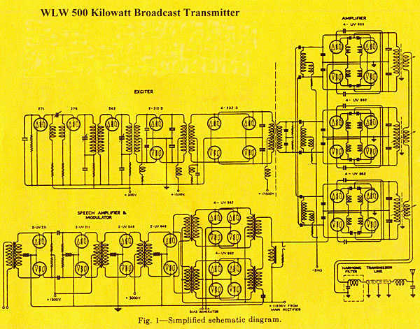
The transmitter was designed with redundancy and cutback (reduced power mode) in mind, giving the transmitter more continuity of service. The final amplifier was divided into 3 separate modules, each using four RCA type UV-898 tubes in push-pull parallel...

The circuit for the localizer is based on a quad-band GSM/GPRS module interfaced with a microcontroller. After initializing the I/Os and UARTs, the microcontroller enters a loop waiting for events, such as the arrival of an SMS or the...
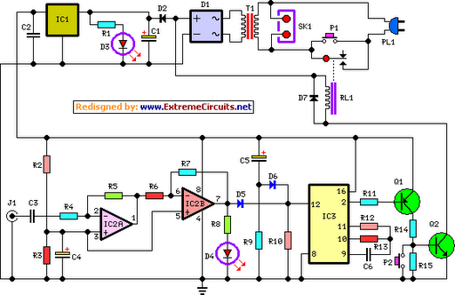
This circuit deactivates an amplifier or any connected device when a low-level audio signal is absent at its input for at least 15 minutes. Activating switch P1 powers the device, enabling operation of any appliance connected to SK1. The...

The circuit presented is an integrated circuit (IC) controlled emergency light. Its key features include automatic activation of the light during mains failure and a battery charger equipped with overcharge protection. In the absence of mains power, relay RL2...
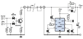
This circuit was designed to transmit commands over an LNB coaxial cable. An LNB (Low-Noise Block downconverter) is commonly used for satellite TV reception and is positioned at the focal point of a satellite dish. The circuit generates a...
This precise one-pulse-per-second clock is constructed using a few common components and is driven by a 50 or 60 Hertz mains supply without any direct connection to it. A beep or a metronome-like click, along with a visible flash,...