
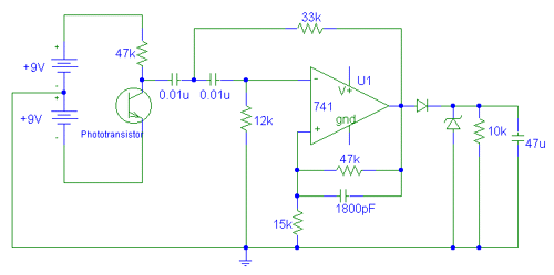
line following robot identifying the line

The circuit for a line-following robot typically incorporates an array of LDRs configured in a way that allows for differential light sensing. The LDRs are arranged in a linear fashion along the front side of the robot. When the robot is positioned over the line, the LDRs that are directly over the black line will show a lower resistance due to reduced light reflection, while the LDRs over the white background will exhibit higher resistance due to increased light reflection.
To process the signals from the LDRs, a microcontroller is employed. The microcontroller reads the voltage levels from each LDR, which can be converted into digital signals using an Analog-to-Digital Converter (ADC) if necessary. Based on the input from the LDRs, the microcontroller can determine the position of the line relative to the robot. If the robot detects that the left LDRs are receiving less light than the right ones, it can adjust its movement to the right, and vice versa.
Additional components in the circuit may include operational amplifiers to amplify the LDR signals for better sensitivity, and a motor driver circuit to control the motors that steer the robot. The motor driver receives commands from the microcontroller based on the processed LDR data, allowing for precise maneuvers along the line.
For optimal performance, calibration of the LDRs may be necessary to account for varying ambient light conditions. This can be achieved by programming the microcontroller to establish baseline readings under different lighting conditions, thus allowing the robot to adapt its line-following behavior accordingly.
In summary, the line-following robot utilizes an LDR array for line detection, a microcontroller for processing the signals, and a motor driver for executing movement commands, forming an integrated system capable of navigating along predefined paths efficiently.To follow the line robot need to identify the line first. Well there are few things you can do to identify a black line on white background or vice versa. One way is use LDR array and tracks the light reflection level. Black line will not reflect the light as white color. Or you can.. 🔗 External reference
Related Circuits
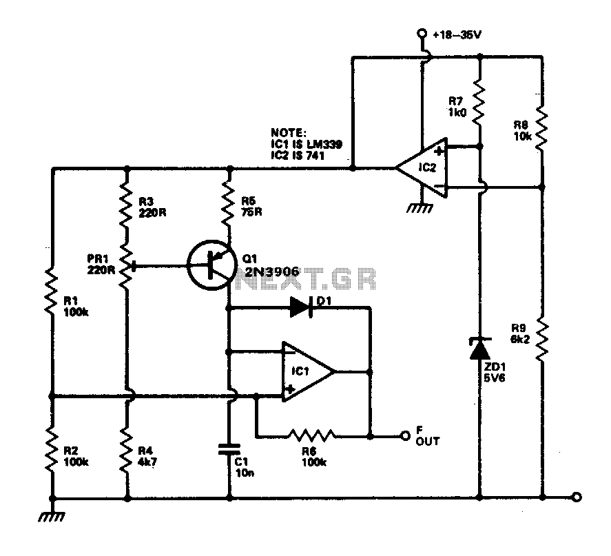
This circuit provides a linear frequency increase of 10 Hz per °C over a temperature range of 0 to 100 °C and can be utilized with logic systems, including microprocessors. The temperature probe Q1, utilizing the Vbe characteristic, changes...
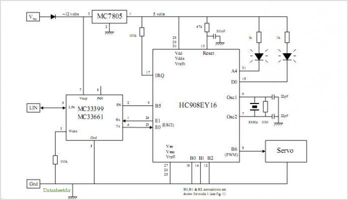
System Oscillator Crystal/Ceramic Oscillator. The following circuit combination of resistors, capacitors, and inductors depicts an equivalent circuit for a crystal or ceramic oscillator. The system oscillator, specifically a crystal or ceramic oscillator, utilizes a combination of passive components, including resistors,...
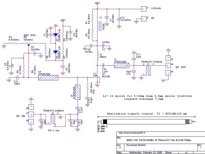
The achievement of this 30 watt amp was thought to take place on a heatsink microprocessor PC. Equipped with its fans, the advantage of this method of cooling was chosen for the fact it is common and not very...
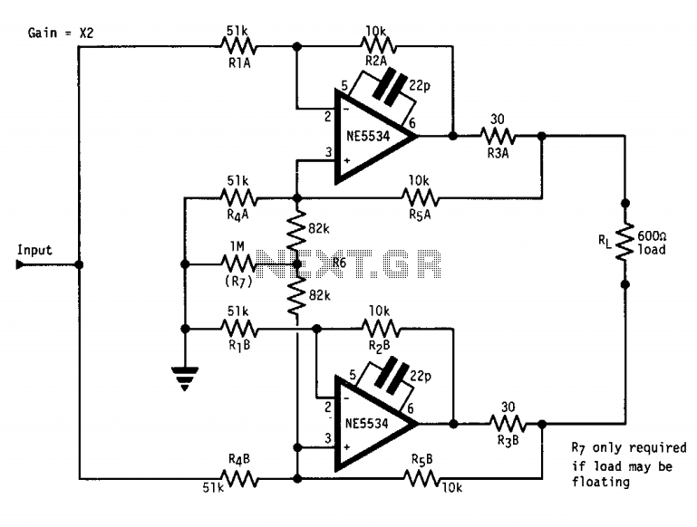
The circuit features a "floating" output, functioning similarly to an isolated transformer winding. The output amplitude remains constant regardless of whether the center or either end of the load is grounded. This is accomplished by ensuring that the output...
When determining how to navigate the robot through the house, the designers recognized the necessity for precise movement to avoid colliding with walls and incurring penalties. To achieve the required movement precision, it was decided that the robot would...
The accuracy of direct linear coupling of analog current signals through an optocoupler is influenced by the linearity of the coupler and its temperature coefficient. Implementing an additional coupler for feedback can enhance linearity, but only if both couplers...