
Measurement Related
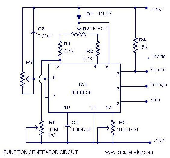
The ICL8038 is a function generator chip capable of producing triangular, square, sine, pulse, and sawtooth waveforms, with simultaneous output of sine, square, and triangular waveforms. Users can control parameters such as frequency, duty cycle, and distortion. This circuit is ideal for beginners and essential for electronics hobbyists. It generates waveforms in the range of 20Hz to 20kHz and requires a dual power supply.
The audio distortion meter is a simple 1kHz device that measures Total Harmonic Distortion (THD) across various loads (2, 4, 8, or 16 ohms). The circuit utilizes a notch filter consisting of an inductor (L1), capacitors (C1, C2), and a resistor (R1) to filter the 1kHz fundamental signal, allowing for straightforward THD calculations.
An audio watt meter is designed to measure amplifier output. Resistor R2 serves as the load and must handle twice the maximum power of the amplifier. The meter scale requires calibration for accurate results. If a 1A bridge is unavailable, it can be constructed using four 1N4007 diodes, and R2 should be rated for twice the amplifier's power.
The sound level meter circuit employs the LM3915 audio level IC to display sound levels from an amplifier or microphone. It includes a peak detector using a BC558 transistor and a 1N4001 diode for enhanced performance. The supply voltage ranges from 3V to 20V, with an audio line voltage input set at 1V peak-to-peak and a maximum input voltage of 1.3V.
The LED thermometer circuit is a precision temperature measurement device based on the LM34 sensor and LM3914 bar graph driver. It can be modified for Celsius readings by replacing the LM34 with an LM35 sensor. The circuit operates on a volt power supply and requires calibration using a voltmeter connected to specific pins.
The audio level meter circuit is valuable for audio enthusiasts, providing essential measurements in audio applications. The dual common emitter amplifier configuration ensures a robust signal amplification, while the adjustable resistor allows for fine-tuning the sensitivity to match the desired output. The inclusion of a 100µA ammeter provides a visual representation of the audio levels, facilitating real-time monitoring.
The ICL8038 function generator circuit is versatile in generating multiple waveform types, making it suitable for various applications, including testing and signal generation. Its ability to produce simultaneous waveforms enhances its functionality, and the control over frequency and distortion parameters allows for precise waveform manipulation.
The audio distortion meter circuit is particularly useful in assessing audio equipment performance, enabling users to measure and analyze THD accurately. The notch filter design is critical for isolating the fundamental frequency, ensuring that only the harmonic distortion is measured.
The audio watt meter serves as a practical tool for evaluating amplifier output, providing insights into power handling and efficiency. The calibration process ensures that users can obtain reliable measurements, making it an essential addition to any audio testing setup.
The sound level meter circuit's integration of the LM3915 IC simplifies the process of measuring sound levels, making it accessible for users without extensive expertise. The peak detector enhances measurement accuracy, allowing for effective monitoring of audio signals.
The LED thermometer circuit exemplifies precision in temperature measurement, with the option for Celsius readings expanding its usability. The straightforward calibration process ensures that accurate temperature readings can be obtained, making it suitable for various applications in electronics and environmental monitoring.Audio Level Meter Description A simple and low cost audio level meter circuit that can be used to measure the audio level of your sound source. This circuit is a valuable tool for those who are interested in audio circuits. The circuit is designed with a flat frequency response in the range of 20Hz to 50Khz. Input sensitivity is 100mV for a FSD on a 100uA ammeter. The circuit is build based on on two common emitter amplifiers, the first stage has a preset resistor R3 (1K) which may be adjusted for a FSD. The last stage is biased to operate at Function Generator Circuit The ICL8038 is a function generator chip, capable of generating triangular, square, sine, pulse and sawtooth waveforms.
From these sine, square & triangular wave forms can be made simultaneously. There is an option to control the parameters like frequency, duty cycle and distortion of these functions. This is the best function generator circuit for a beginner to start with and is of course a must on the work bench of an electronics hobbyist.
The circuit here is designed to produce waveforms from 20Hz to 20 kHz. The ICL 8038 has to be operated from a dual power supply. Function Audio Distortion Meter Description Here is a simple 1KHz audio distortion meter that can measure the Total Harmonic Distortion (THD) on any load at any out put power. Here you have the option to select 2, 4, 8 or 16 Ohm loads. The circuit works by filtering the 1 kHz fundamental signal using a notch filter comprising of L1, C2, C1, R1.
With a little time and calculation you can get the correct THD of your amplifier in such a simple way. Audio Distortion Meter Circuit Diagram with Parts List. Notes Inductor L1 is a UTC VC 15 variable inductor. If this is not available try Audio Watt Meter Description This is an easy trick to measure the output of an amplifier.
Here resistor R2 acts as the load for for the amp and it should be able to withstand twice the maximum power of the amp you are going to measure. The meter scale must be calibrated and with a little effort you can get good results. Audio Watt meter Circuit Diagram with Parts List. Notes If 1A bridge is not available, make one with four 1N 4007 Diodes. The resistor R2 must be twice the power of amp you are going to measure. To calibrate Sound Level Meter Circuit Description This is a one chip sound level meter that can be use for displaying sound level of an amplifier or simply the sound level from a microphone.
The heart of the circuit is IC LM 3915 Audio level IC. Even though it is a stand alone IC, a peak detector based on Transistor BC 558 and diode 1N4001 is also included for better performance. Tips Supply voltage can be from 3V to 20V. The input is set for audio line voltage (1V peak to peak) and has a max input voltage of 1. 3V. To make the circuit LED Thermometer Temperature Measurement Circuit Description The circuit given here is a precision LED bar graph Fahrenheit thermometer, which can be used as a temperature measurement circuit, build around IC LM 34 (sensor) and IC LM 3914 (bar graph driver).
The circuit can be modified to read in degree Celsius by replacing sensor LM 34 with LM 35. Both are inter changeable. The circuit operates of a volt power supply. To calibrate the circuit, you will need a voltmeter. Power the circuit. Ground the negative lead of the volt meter and connect the positive lead to pins 6 and 🔗 External reference
Related Circuits
AMP-04 is a single-supply, single resistor gain adjustment circuit with an input voltage drift of less than 150 pV, a current drift of 5 nA, and a temperature drift of 8 pA/°C. The gain nonlinearity is 0.005% of the...
The chips that are classified as "working well" produce approximately 300 mV when exposed to a laser pointer and between 40 to 80 mV when illuminated by LED light. Voltages around 100 mV were recorded in a sunlit environment,...
Watch the video below to gain a better understanding of how a light-emitting diode (LED) functions. An LED is recognized as one of the most effective optoelectronic devices available. This device emits a relatively narrow bandwidth of visible or...
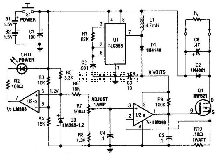
Useful for low-resistance measurements, this 1-A current source will produce 1 A in unknown resistance Rx. For best results, Rc should be less than 1 to 2, because only 3 V are available. Ul is a flyback converter to...
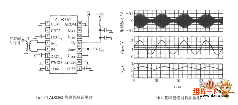
The UTGT side of the AD8362 can be utilized to create a demodulation circuit. It extracts the envelope from the RF amplitude and converts it into a low and mid-frequency signal prior to demodulation. The waveforms associated with the...
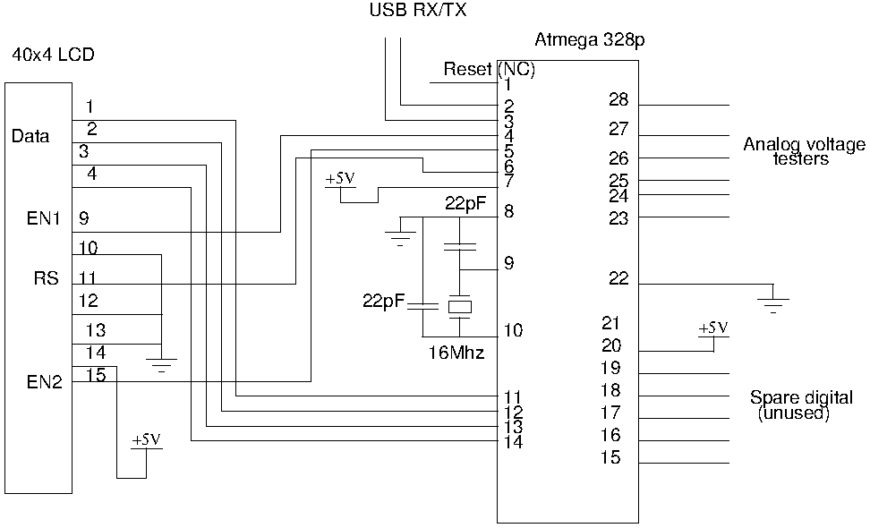
Drive a four-line LCD panel using an Arduino. The project initially aimed to control the LCD for displaying arbitrary information but evolved to include functionalities such as timekeeping, EEPROM read/write operations from the Atmel 328p, and voltage measurement. Multiple...