
Notes on the Wenzel low power AM transmitter schematic
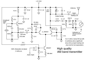
The Wenzel transmitter design is a notable example of effective low-power amplitude modulation (LPAM) transmitter architecture, favored for its simplicity and performance. The circuit typically employs a differential amplifier configuration, which is crucial for modulating the audio signal onto the carrier frequency. The design incorporates a tuned output circuit, often consisting of an LC resonant circuit or a crystal oscillator, to establish the operating frequency.
One of the key features of the Wenzel circuit is its adaptability, allowing users to substitute components based on availability and personal preference. For example, some users have successfully replaced the original transistors with planar transistors like the 2N5551, which can handle higher voltages, thereby enhancing the transmitter's performance. This flexibility extends to the output loading; users have observed that incorporating a load resistor across the output tuned circuit significantly improves linearity and reduces distortion, particularly when the antenna is not optimally matched.
The importance of antenna configuration cannot be overstated. The Wenzel circuit is designed to work with short antennas, which inherently have low radiation resistance. Users have noted that a load resistor of 500 to 1000 ohms can enhance performance by providing a better match and improving the overall efficiency of the transmission. Additionally, experimenting with antenna lengths and matching networks can yield substantial improvements in range and signal clarity.
In summary, the Wenzel transmitter represents an effective solution for hobbyists interested in low-power AM transmission. Its design encourages experimentation and modification, allowing users to tailor the circuit to their specific needs while maintaining good sound quality and manageable range. The discussions surrounding this circuit exemplify the collaborative nature of the amateur radio community, where shared experiences and insights contribute to ongoing improvements in transmitter design and performance.In many discussions of LPAM transmitter design you will hear or read references to "the Wenzel circuit" or "the Wenzel transmitter. " These refer to the clever transmitter design downloadable at During the mid 1990s and early 2000s, this was the best available AM transmitter circuit if you wanted to build something yourself for around-the-house "yardcasting.
" The range is limited but the sound quality is good compared to other homebrew circuits that were published at the time. An updated, illustrated web page about this circuit, including a modified version with a different output section, is published by Mr Wenzel himself at Below are some comments that were published in various newsgroups about the original version of the circuit.
It`s fascinating to see what a detailed analysis and spirited discussion this circuit received! Is that the little transmitter that Syl says is among the best he`s tried If so, I am using that as a basis for my design. If an LC works in place of the crystal, I`ll certainly give it a try. - Joe Yes it is. It`s also on my website. The only really good design so far. I use planar transistors (2N5551) to replace the 2n4401 because I had them on hands by the dozen and I can drive them with 150V.
(like I need it. ) I suspect any 2SCxxxx from the junk box might also work. Now that Sal sent me a crystal, I`ll replace the LC I replace it with. I think Bill M. also did this with his. Even on the scope. At least not within it`s "useful" range with wrong antenna loading. With the proper loading (which is somewhat important for increased range), sound is excellent. If unproperly loaded, close to the transmitter the sound is excellent too but the range suffers a *lot. It does distort outside the "useful" range but I think it is caused by the weak signal (some of my radios are better than other though)as the ouput is very clean close to the transmitter.
I tune the antenna using an adjustable coil (using a ferrite) I found in my junk box. If you look closely at the "diff amp" circuit at you will notice a 470 ohm resistor paralleling the output tuned circuit. This resistor is essentially the only load on the output, since the short antenna doesn`t even come close to loading the output.
Without the resistor the tank just rings horribly and sort of loosely follows the modulation envelope. With the resistor the output is very clean and linear and is quite unaffected by the antenna. 99% of the "100 mw" power is absorbed in this resistor, but the waveform is linear. The Vectronics doesn`t have a load resistor. It does have a better output matching circuit. It has a "reverse" pi network (low impedance in and high impedance out). This maximized the voltage presented to a short antenna with its very low radiation resistance to improve the loading (marginally).
The Vectronics circuit would benefit with a load resistor of say 500 - 1000 ohms across C8 or a larger resistor of say 20k - 50k from the antenna terminal to ground. This loading problem is common to all BC frequency transmitters with short antennas. You just can`t get very much of the power to go to a short antenna. Another solution is to use an antenna of several hundred feet or more and a good antenna matching network.
Play a little with the osc. resistors to get a better sinewave. I changed a few resistors until I got an almost perfectly uniform sinewave on the scope. For some reasons, on some radios the signal got much better. I`ve never really haggled much over the output loading inductance because I have used `illegal` antenna lengths and the coverage area has been sufficient for my needs. But I wonder if a 3 foot antenna would really present much difference at 1. 6 versus 1. 0 Both present an extremely high impedance. I think his measure of "half" the reading is based on reflection (VSWR) showing up on the meter. I suppose ideally a tunable inductor that would go up to maybe 1. 5mh Exactly what 🔗 External reference
Related Circuits
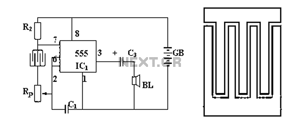
Figure 1 illustrates a circuit diagram related to an audio circuit that incorporates a resistance between two leads connected to a rain alarm probe. Figure 2 demonstrates the connection of a capacitor to the probe within the audio circuit....

The complete hardware schematic of the Night Light Saver V6.0 includes an AC line protected by a 1A fuse (F1). Any short circuit caused by the components of the saver will blow the fuse. Resistor R1 and capacitor C1...
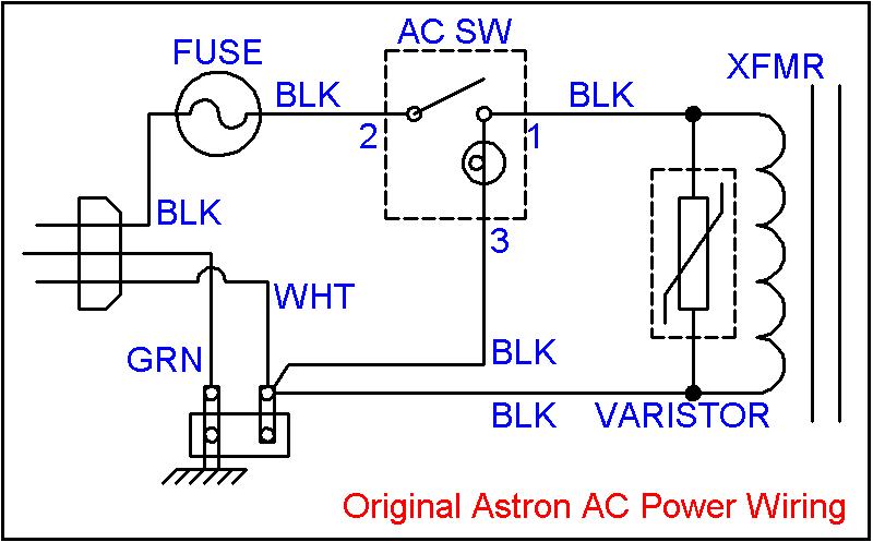
Owners of large 500-watt and higher Astron linear power supplies, as well as large HF amplifiers, are familiar with the "GNNNNnng" sound that occurs upon power-up. This noise is caused by the high inrush (surge) current flowing into the...
For some time, a method to measure laser power has been sought without incurring significant expenses on a power meter. Initially, constructing such a device may seem unfeasible. To create a cost-effective laser power measurement system, one approach involves utilizing...
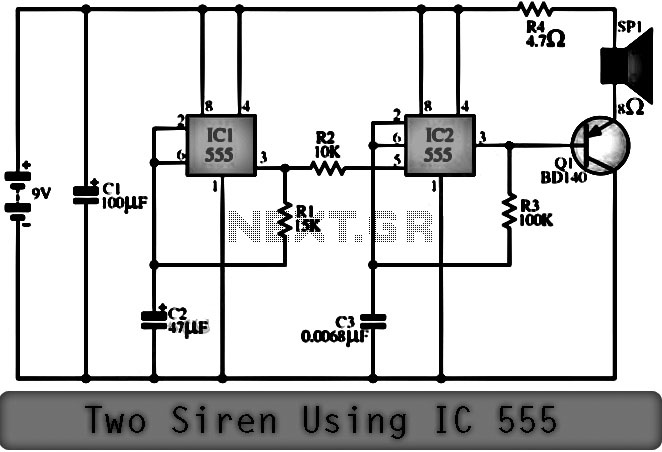
The function of the Two Siren Sound Circuit utilizing IC 555 is divided into three parts: low frequency production, manufacturing of a shrill frequency, and low frequency output. The low frequency is generated by IC1, which is connected to...
This circuit utilizes a 74HC14 hex Schmitt trigger inverter as a square wave oscillator to drive a small signal transistor configured in a class C amplifier setup. The frequency of the oscillator can be either fixed using a crystal...
Warning: include(partials/cookie-banner.php): Failed to open stream: Permission denied in /var/www/html/nextgr/view-circuit.php on line 713
Warning: include(): Failed opening 'partials/cookie-banner.php' for inclusion (include_path='.:/usr/share/php') in /var/www/html/nextgr/view-circuit.php on line 713